
Installation Instructions
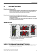

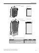

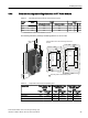


Table Of Contents
- Power Module PM230, IP20 / Push-through technology (PT)
- Legal information - Warning notice system
- Table of contents
- 1 Changes in this manual
- 2 Fundamental safety instructions
- 3 Introduction
- 4 Installing/mounting
- 5 Connecting
- 6 Service and maintenance
- 7 Technical specifications
- 7.1 Overload capability of the inverter
- 7.2 Cable cross-sections and tightening torques
- 7.3 Electromagnetic compatibility - overview
- 7.4 Ambient conditions
- 7.5 General technical data
- 7.6 Detailed technical data
- 7.7 Restrictions for special ambient conditions
- 7.8 Electromagnetic compatibility of variable-speed drives
- 8 Spare parts and accessories
- A Appendix
- Index

Table 4-6 Drilling dimensions, cooling air clearances [mm] and fixing [Nm]
Frame
size
Section of the control cabinet Cooling air clearances
1)
Fixing
a b c d e Top Bottom Front Screws/torque
FSA 103 106 27 198 88 80 100 100 8 x M5 / 3.5
FSB 148 134 34.5 304 116 80 100 100 8 x M5 / 3.5
FSC 123 174 30.5 365 156 80 100 100 10 x M5 / 3.5
1)
You can mount the Power Modules without any lateral cooling air clearance. For tolerance reasons,
we recommend a lateral clearance of 1 mm.
4.4.2.1 Mounting the shield plate
The shield plates and fixings screws are included in the inverter accessory kit.
Figure 4-5 Mounting the shield plate
Installing/mounting
4.4 Mounting the Power Modules
Power Module PM230, IP20 / Push-through technology (PT)
36 Hardware Installation Manual, 08/2016, A5E34331322B AB