2012 Valve & Valve Actuator Catalog Siemens Industry, Inc. 1000 Deerfield Parkway Buffalo Grove, IL 60089-4513 USA Tel. 847-215-1000 Siemens Building Technologies, Ltd. 2 Kenview Blvd. Brampton, Ontario L6T 5E4 Canada Tel. 905-799-6649 Ready to place an order? Contractor or Wholesalers, call 1-888-593-7876 Siemens Solution Partners, call 1-800-516-9964 Canadian Customers, call 1-800-236-2967 All other customers, call your local Siemens branch Siemens Online Ordering, go online to www.usa.siemens.
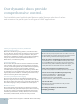
Our dynamic duos provide comprehensive control. Fast installation and sophisticated features make Siemens selection of valves and actuators the perfect pair for all types of HVAC applications. A history of engineering excellence, backed with superior customer support We’ve been manufacturing energy-efficient, cost-effective valves for over 100 years. Siemens valves are relied on to improve comfort in all types of environments, in all types of facilities.
www.usa.siemens.
Table of Contents Zone Valves Introduction . . . . . . . . . . . . . . . . . . . . . . . . . . . . . . . . . . . . . . . . . . . . . . . . 6 Two- & Three-way Zone Valves—1/2 to 1-inch . . . . . . . . . . . . . . . . . . . . . . . . . . . . . . 7 SFA/SFP Series Electronic Valve Actuators . . . . . . . . . . . . . . . . . . . . . . . . . . . . . . . . 8 SSA/SSP Series Electronic Valve Actuators . .
Ball Valves Introduction . . . . . . . . . . . . . . . . . . . . . . . . . . . . . . . . . . . . . . . . . . . . . . . 109 Two- & Three-way Ball Valves . . . . . . . . . . . . . . . . . . . . . . . . . . . . . . . . . . . . . .110 Two-way Ball Valve Assemblies—1/2 to 2-inch . . . . . . . . . . . . . . . . . . . . . . . . . . 114-118 Three-way Ball Valve Assemblies—1/2 to 2-inch . . . . . . . .
Table of Contents Accessories & Service Kits (continued) Retainer Clamp Kit . . . . . . . . . . . . . . . . . . . . . . . . . . . . . . . . . . . . . . . . . . . .172 Service Flanges . . . . . . . . . . . . . . . . . . . . . . . . . . . . . . . . . . . . . . . . . . . . . 172 Service Kits . . . . . . . . . . . . . . . . . . . . . . . . . . . . . . . . . . . . . . . . . . . . . . . .172 Lower Seat Tools . . . . . .
599 Series Zone Valves More options for zone control Zone Valves in 1/2 to 1-inch sizes provide excellent control of fan coils, unit ventilators and other applications where on/off, floating or proportional control is required. All-metal plugs and seat deliver superior control of water and glycol solutions with NPT or sweat connections. Proven linear stroke globe valve design — no “water hammer” effects caused by rubber paddles or flappers.
Two- and Three-Way Zone Valves 1/2 to 1" Normally Open, Normally Closed, Diverting ANSI Class 125 Description Specifications Two- and Three-Way Zone Valves have a 1/10-inch (2.5 mm) stroke. The Zone Valves work with any SFA/SFP Series, SSA/SSP Series electric actuator, or with the STA/STP Series Thermic actuator. The actuators accept one of either 24 Vac or 120 Vac power supply signal to provide on/off, floating or 0 to10 Vdc control. Line Size............................................
599 Series Zone Valves Two-Way NPT Zone Valve. Three-Way Sweat Zone Valve. Two-Way Zone Valve Body Dimensions Three-Way Zone Valve Body Dimensions C C VE0257R1 B B VE0256R1 A A 2-Way Valve Valve Size in. (mm) A 3-Way Valve B C 0.5 (15) 2.76 (70) 1.63 (41.5) 1.00 (25.4) 0.75 1.0 (20) (25) 2.76 3.50 (70) (89) 1.77 2.10 1.00 (25.4) 1.00 (25.4) 0.5 0.75 1.00 (15) (20) (25) 2.66 2.76 3.50 (66) (70) (89) 1.48 (38) 1.63 (41.5) 1.77 (45) (45) (54) Weight Valve Size lb. (kg) in.
SFA/SFP Series Electronic Valve Actuator Spring Return 24, 120, 208, or 277 Vac Description Specifications The SFA/SFP Series of Electronic Valve Actuators accepts 24, 120, 208, or 277 Vac power supply signal to provide two-position control. This actuator works with Zone Valves with 1/10-inch (2.5 mm) stroke. Power Supply Operating Voltage .......................................
599 Series Zone Valves SFA/SFP Series Electronic Valve Actuator. SFA/SFP Series Actuator Dimensions W W1 W1 H1 H H1 VE0263R1 VE0264R1 H W Service Envelope for Two-Way Valve Assembly Service Envelope for Three-Way Valve Assembly VE0958R1 3.4 (85.2) 4.4 (111) 2.3 (58) Dimensions shown in inches (mm). Valve Size in. (mm) 0.5 (15) 0.75 (20) 1.00 (25) Valve Center Line to Top of Actuator H1 2-Way 3-Way 4.38 (112) 4.38 (112) 4.38 (112) 4.38 (112) 4.38 (112) 4.
SSA/SSP Series Electronic Valve Actuator Non-Spring Return 24 Vac, Floating or 0-10V Control Description Specifications The SSA/SSP Electronic Valve Actuator requires a 24 Vac power supply and receives a 0 to 10 Vdc signal or a floating control signal to control a valve. This actuator is designed to work with Zone Control Valves with a 1/10-inch (2.5 mm) stroke and a threaded valve bonnet that fits the actuator. Power Supply Operating Voltage .............................................................
599 Series Zone Valves SSA/SSP Series Electronic Valve Actuator. SSA/SSP Series Actuator Dimensions H W W W1 W1 H H1 H1 Gap=.06 (1.5) Gap=.06 (1.5) C VE0278R1 VE0279R1 C Service Envelope for Two-Way Valve Assembly EA01029R1 3.90 (98.5) Valve Size in. (mm) 0.5 (15) 0.75 (20) 1.00 (25) Service Envelope for Three-Way Valve Assembly 3.52 (89.5) 1.90 (48) 3.27Dimensions shown in inches (mm).
Two- and Three-Way Zone Valve Assemblies 1/2 to 1", ANSI Class 125 Electronic Spring Return and Non-Spring Return Actuators NO/NC 1/2 to 1" Spring Return Actuator NC NO NO 2P 120 Vac 2-Way Valve Body Part No. Valve Size in.
599 Series Zone Valves Two-Way Spring Return Two-Way Non-Spring Return Diverting 1/2 to 1" 3-Way Valve Body Part No. Three-Way Spring Return Spring Return Actuator AB→A NO AB→A NC 2P 120 Vac Valve Size in.
Thermic Actuators Spring Return 24 Vac/dc Description Specifications Thermic Actuators require a 24 Vac/Vdc control signal to provide two-position, NO or NC control. This actuator is designed to work with Zone Valves with a 1/10-inch (2.5 mm) stroke. Power Supply Supply Voltage............................................24 Vac, 50 to 60 Hz or 24 Vdc Power Consumption.....................Normal Operation 2.5W; Power on 6 VA Switch-on Current (transient)....................................................
599 Series Zone Valves Thermic Electronic Valve Actuator. Thermic Actuator Dimensions W W W1 W1 H H H1 C H1 VE0280R1 VE0281R1 C Two-Way Valve Assembly Service Envelope Three-Way Valve Assembly Service Envelope EA0998R1 2.44 (62) 1.81 (46) 1.71 (43.4) Dimensions shown in inches (mm). Valve Center Line to Top of Actuator H1 Valve Size 2-Way 3-Way in.
Zone Valve Assemblies 1/2 to 1", ANSI Class 125 Thermic Spring Return Actuators 2-Way Spring Return NO/NC 1/2 to 1" Spring Return Actuator NO NC 2P 24 Vac 2-Way Valve Body Part No. Valve Size in. Flow Rate Cv Close Off psi STP71 STA71 3-Way Spring Return Diverting 1/2 to 1" 3-Way Valve Body Part No. Spring Return Actuator AB→A NO AB→A NC 2P 24 Vac Valve Size in. Flow Rate Cv Close Off psi NPT Connection 599-00210 599-00211 599-00214 599-00212 599-00213 1/2 3/4 1 1.0 2.5 4.0 4.1 7.
Powermite Globe Valves Simple to configure, simple to install MZ and MT Series Powermite Globe Valves feature a compact housing design for ease of installation, even in tight spaces. Direct-coupled technology allows fast connection of valve body and actuator, without requiring tools. 100:1 resolution with <2 % hysteresis provides greater control. ANSI Class 250 valve body with metal-to-metal seating surfaces create the tightest seal possible and ensure long-lasting, reliable performance.
Two- & Three-Way MZ Series Globe Valves 1/2 to 1" Normally Open, Normally Closed, Mixing ANSI Class 250 Description Specifications Powermite MZ Series Valve bodies work with the SSB electronic actuator with a 7/32-inch (5.5 mm) stroke. Valve Size ...............................................................1/2 to 1” (15 to 25 mm) Features Seat Style .............................................................................
Powermite Globe Valves Powermite MZ Series Two-Way Globe Valve. Powermite MZ Series Three-Way Globe Valve. Two-Way Valve Dimensions Female NPT by Female NPT (FxF) Female NPT by Union Male (FxUM) Angle Female by Union Male (AFxUM) Dimensions Valve Size in.
Two- & Three-Way MZ Series Globe Valves 1/2 to 1" Normally Open, Normally Closed, Mixing ANSI Class 250 Two-Way Valves Product Ordering Normally Open or Normally Closed, Brass Trim Valve Size Flow Rate Normally Open in. (mm) Cv (Kvs) Part No. 1/2 (15) 0.4 (0.34) 599-01115 1/2 (15) 0.63 (0.54) 599-01117 1/2 (15) 1 (0.85) 599-01119 1/2 (15) 1.6 (1.37) 599-01121 Female x Female 1/2 (15) 2.5 (2.14) 599-01123 1/2 (15) 4 (3.42) 599-01126 3/4 (20) 6.3 (5.38) 599-01129 1 (25) 10 (8.55) 599-01131 1/2 (15) 0.4 (0.
Powermite Globe Valves Powermite MZ Series Two-Way Globe Valve. Powermite MZ Series Three-Way Globe Valve. Three-Way Valves Product Ordering Mixing, Brass Trim in. 1/2 1/2 1/2 1/2 1/2 1/2 3/4 1 Valve Size Flow Rate (mm) Cv (Kvs) (15) 0.4 (0.34) (15) 0.63 (0.54) (15) 1 (0.85) (15) 1.6 (1.37) (15) 2.5 (2.14) (15) 4 (3.42) (20) 6.3 (5.38) (25) 10 (8.55) There are no repair parts for this product. Replace the entire valve body if inoperative. Part No.
SSB Series Electronic Valve Actuators Non-Spring Return 24 Vac, Proportional or Floating 3-Position Description Specifications SSB61U Electronic Valve Actuators require a 24 Vac supply and receive a 0 to 10 Vdc control signal to proportionally control a valve. SSB81U Electronic Valve Actuators require a 24 Vac supply floating control signal to provide three-position control. SSB series actuators are designed to work with Powermite MZ Series Valves with a 7/32-inch (5.
Powermite Globe Valves SSB Series Electronic Valve Actuator. Dimensions 3-1/8 (79) 3-7/8 (98) EA0589R2 1-7/8 (48) 3-1/4 (83) Dimensions shown in inches (mm). Center Line to Top of Actuator Valve Size in.
Two- and Three-Way MZ Series Globe Valve Assemblies 1/2 to 1", ANSI Class 250 Electronic, Non-Spring Return Actuators NO/NC 1/2 to 1" Non-Spring Return Actuator Valve 2-Way Size Valve Body in. Part No. Normally Open Assemblies Flow Close Rate Off Floating 3P 0-10 V SSB61U Cv psi SSB81U 0.4 0.63 1 1.6 2.5 4 6.3 10 60 60 60 60 35 35 30 30 254-01115 254-01117 254-01119 254-01121 254-01123 254-01126 254-01129 254-01131 0.4 0.63 1 1.6 2.5 4 6.
Water Mixing 1/2 to 1" 3-Way Valve Body Part No. Mixing Assemblies Powermite Globe Valves Powermite MZ Series Two-Way Globe Valve & Actuator Assembly Powermite MZ Series Three-Way Mixing Globe Valve & Actuator Assembly Non-Spring Return Actuator Valve Size in. Flow Close Rate Off Floating 3P 0-10 V SSB61U Cv psi SSB81U 0.4 0.63 1 1.6 2.5 4 6.
Two- & Three-Way MT Series Globe Valves 1/2 to 1" Normally Open, Normally Closed, Mixing ANSI Class 250 Description Specifications The Powermite MT Series Globe Valves are designed to work with either a pneumatic or electronic actuator with a 7/32-inch (5.5 mm) stroke. Compatible actuators deliver a minimum of 67 lbf. (300 N) of force. Valve Size ...............................................................
Powermite Globe Valves Powermite MT Series Two-Way Globe Valve. Powermite MT Series Three-Way Globe Valve. Two-Way Valve Dimensions Female NPT by Female NPT (FxF) Female NPT by Union Male (FxUM) Angle Female by Union Male (AFxUM) Dimensions Valve Size In. 1/2" (15 mm) 3/4" (20 mm) 1" (25 mm) A B C 1-3/8" (35 mm) 1-5/8" (41 mm) 1-15/16" (49 mm) FxF & FxUM NO NC 2-1/4" (57 mm) 2-3/8" (59 mm) 2-3/4" (69 mm) AFxUM 2-15/16" (74 mm) — — NO D Weight E FxF FxUM AFxUM 1.3 lb. (0.6 kg) 1.8 lb. (0.
Two- & Three-Way MT Series Globe Valves 1/2 to 1" Normally Open, Normally Closed, Mixing Two-Way Valves Product Ordering Normally Open or Normally Closed, Brass or Stainless Steel Trim Connection Female x Female Female x Union Male Angle Female x Union Male Brass Trim Normally Open Part No. Brass Trim Normally Closed Part No. Stainless Steel Trim Normally Open Part No. Stainless Steel Trim Normally Closed Part No.
Powermite Globe Valves Powermite MT Series Two-Way Globe Valve. Powermite MT Series Three-Way Globe Valve. Three-Way Valves Product Ordering Mixing, Brass or Stainless Steel Trim in. Valve Size (mm) Cv Flow Rate (Kvs) Stroke (in.) Brass Trim Part No. Stainless Steel Trim Part No. 1/2 (15) 0.4 (0.34) 7/32 599-02064 599-02072 1/2 (15) 0.63 (0.54) 7/32 599-02065 599-02073 1/2 (15) 1 (0.85) 7/32 599-02066 599-02074 1/2 (15) 1.6 (1.37) 7/32 599-02067 599-02075 1/2 (15) 2.
Powermite 2" Pneumatic Valve Actuators For 1/2 to 1" Valve Bodies Only Description Specifications The Powermite Two-inch Pneumatic Valve Actuator is designed for use with the 1/2 to 1-inch Powermite MT Series Terminal Unit Valves with a 7/32-inch (5.5 mm) stroke. Effective Diaphragm Area ................................................ 3.4 in.2 (22 cm2) Features Span ......................................................................................
Powermite Globe Valves Powermite 599 Series 2" Pneumatic Valve Actuator. Dimensions Valve Size in. 1/2" (15 mm) 3/4" (20 mm) 1" (25 mm) Center Line to Top of Actuator H1 3-1/16" (78 mm) 3-1/16" (78 mm) 3-5/16" (84 mm) Service Height Actual Width H W 11" (280 mm) 11" (280 mm) 11-1/4" (285 mm) 4" (100 mm) 4" (100 mm) 4" (100 mm) Service Width W 1 10" (250 mm) 10" (250 mm) 10" (250 mm) 1. Recommended service dimensions to allow access to the product.
SSC Series Electronic Valve Actuators Spring Return or Non-Spring Return 24 Vac, Floating or Proportional Control Description Powermite MT Series Electronic Valve Actuators require a 24 Vac supply to control Powermite MT series valves with a 7/32-inch (5.5 mm) stroke and a threaded valve bonnet that fits the actuators. SSC61 Electronic Valve Actuators require a 24 Vac supply and receive a 0 to 10 Vdc control signal. SSC81 Electronic Valve Actuators receive a 3-position (floating) control signal.
Powermite Globe Valves SSC Series Electronic Valve Actuator. 0 2 (48) 4.4 (110.8) 3.5 (89) Dimensions .85 (21.6) 1 EA1159R1 4.5 (115.1) 5.5 (140) Dimensions shown in inches (mm). Valve Size in.
SQS Series Electro-Mechanical Valve Actuators Spring Return or Non-Spring Return 24 Vac, Floating or Proportional Control Specifications Description Powermite SQS65 and SQS65.5 Electronic Valve Actuators require a 24 Vac supply and receive a 0 to 10 Vdc or a 0 to 1000 Ohm control signal to proportionally control a valve. SQS85.53 electronic valve actuators require a 24 Vac supply and receive a floating control signal to provide floating control.
Powermite Globe Valves SQS Series Electronic Valve Actuator. Dimensions Dimensions shown in inches (mm). Valve Size in.
Two- and Three-Way MT Series Globe Valve Assemblies 1/2 to 1", ANSI Class 250 Pneumatic, Spring Return Actuators NO/NC 1/2 to 1" Spring Return Actuator Valve 2-Way Size Valve Body Part No. in. Normally Open Assemblies Flow Rate Cv 3-8 psi (21-55 kPa) 8-13 psi (55-90 kPa) 10-15 psi (69-103 kPa) 599-01088 599-01088 599-01088 Close-off psi — Brass Trim 599-02030 599-02032 599-02034 599-02036 599-02038 599-02041 599-02044 599-02046 1/2 3/4 1 0.4 0.63 1 1.6 2.5 4 6.
Water Mixing 1/2 to 1" 3-Way Valve Body Part No. Powermite Globe Valves Powermite MT Series Two-Way Globe Valve & Pneumatic Actuator Assembly Powermite MT Series Three-Way Mixing Globe Valve & Pneumatic Actuator Assembly. Spring Return Actuator Valve Size in.
Two-Way MT Series Globe Valve Assemblies 1/2 to 1", ANSI Class 250 Electronic, Spring Return or Non-Spring Return Actuators NO/NC 1/2 to 1" Spring Return Actuator Valve 2-Way Size Valve Body Part No. in. Normally Open Assemblies Flow Close Rate Off Non-Spring Return Actuator Floating 0-10 V Floating 0-10 V SSC81U SSC61U 259-02030 259-02032 259-02034 259-02036 259-02038 259-02041 259-02044 259-02046 261-02030 261-02032 261-02034 261-02036 261-02038 261-02041 261-02044 261-02046 Cv psi SSC81.
Powermite Globe Valves Powermite MT Series Two-Way Globe Valve & Actuator Assembly. NO/NC 1/2 to 1" Spring Return Actuator Valve 2-Way Size Valve Body Part No. in. Normally Open Assemblies Flow Close Rate Off Non-Spring Return Actuator Floating 0-10 V 0-10 V SQS65.5U SQS65U Cv psi SQS85.53U 0.4 0.63 1 1.6 2.5 4 6.3 10 160 160 160 160 85 85 70 70 266-02030 266-02032 266-02034 266-02036 266-02038 266-02041 266-02044 266-02046 0.4 0.63 1 1.6 2.5 4 6.
Three-Way MT Series Globe Valve Assemblies 1/2 to 1", ANSI Class 250 Electronic, Spring Return or Non-Spring Return Actuators Powermite MT Series Three-Way Mixing Globe Valve & Actuator Assembly. Water Mixing 1/2 to 1" 3-Way Valve Body Part No. Mixing Assemblies Spring Return Actuator Floating Valve Size in. Flow Close Rate Off Non-Spring Return Actuator 0-10 V Cv psi SSC81.5U SQS85.53U SSC61.5U 0.4 0.63 1 1.6 2.5 4 6.
Flowrite Globe Valves Over 50 years of legendary performance Since 1934, Flowrite has been recognized as the best globe valve in the HVAC control market. Compatible with piping line sizes ranging from 1/2 to 6-inch (Cv range 1.0 to 400), it is an excellent choice for small to large air handling units and for central plant applications. Simply specify the valve and electronic or pneumatic valve actuator configuration that meets your specific requirements.
Two-Way Globe Valves 1/2 to 2", Equal Percentage or Linear Flow Normally Open or Normally Closed ANSI Class 250 Description Specifications Designed to work with either a pneumatic or electronic actuator with a 3/4-inch (20 mm) stroke, the Flowrite Two-way Globe Valves are available in ANSI Class 250 for Normally Closed or Normally Open action. Valve Size ...............................................................1/2 to 2” (15 to 50 mm) Features Action ..............................................
Flowrite Globe Valves Flowrite Two-Way Globe Valve. Two-Way Valve Dimensions Female NPT by Union Female (FxUF) Female NPT by Female NPT (FxF) Valve Size in.
Three-Way Globe Valves 1/2 to 2" Mixing ANSI Class 250 Description Specifications Designed to work with either pneumatic or electronic actuators with a 3/4-inch (20 mm) stroke, the Flowrite Three-way Globe Valves are available in ANSI Class 250. Valve Size ...............................................................1/2 to 2” (15 to 50 mm) Features Seat Style .............................................................................
Flowrite Globe Valves Flowrite Three-Way Globe Valve. Three-Way Valve Dimensions Union Female x Union Female x Union Female (UFxUFxUF) Female NPT x Female NPT x Female NPT (FxFxF) Dimensions Weight Valve Size in.
Two-Way Globe Valves 1/2 to 2", Equal Percentage or Linear Flow Normally Open or Normally Closed ANSI Class 250 Equal Percentage, Two-Way Globe Valve Body Product Ordering Brass and Stainless Steel Trim Connection Female x Female Female x Union Female Female x Union Male Union Female x Union Female 48 Valve Size in.
Flowrite Globe Valves Flowrite Two-Way Globe Valve. Linear, Two-Way Globe Valve Body Product Ordering Stainless Steel Trim Connection Female x Female Female x Union Female Female x Union Male Union Female x Union Female Valve Size in. (mm) Flow Rate Cv (Kvs) Stroke (in.) 1/2 1/2 1/2 1/2 3/4 1 1-1/4 1-1/2 2 1/2 1/2 (15) (15) (15) (15) (20) (25) (32) (40) (50) (15) (15) 1 1.6 2.5 4 6.3 10 16 25 40 1 1.6 (0.9) (1.4) (2.2) (3.4) (5.4) (8.6) (14) (22) (34) (0.9) (1.
Three-Way Globe Valves & Flowrite Valve Actuators 1/2 to 2" Mixing Pneumatic & Electronic Actuators Three-Way Globe Valve Body Product Ordering Brass and Stainless Steel Trim Valve Size Flow Rate Stroke in. (mm) Cv (Kvs) (in.) Standard-Temperature Packing — 20 to 250ºF (-7 to 120ºC) 1/2 (15) 1 (0.9) 3/4 1/2 (15) 1.6 (1.4) 3/4 1/2 (15) 2.5 (2.2) 3/4 1/2 (15) 4 (3.4) 3/4 Female x Female 3/4 (20) 6.3 (5.4) 3/4 1 (25) 10 (8.6) 3/4 1-1/4 (32) 16 (14) 3/4 1-1/2 (40) 25 (22) 3/4 2 (50) 40 (34) 3/4 1/2 (15) 1 (0.
Flowrite Globe Valves Flowrite Electro-Mechanical Non-spring Return Actuator Flowrite Three-Way Globe Valve. Flowrite Globe Valve Actuators Product Ordering Spring Return and Non-Spring Return Description 4" Pneumatic 8" Pneumatic and Pneumatic w/Positioner Electro-Mechanical Electro-Hydraulic Part No. Actuator Prefix Code 3-8 psi (21-55 kPa) 599-01081 268 5-10 psi (34-69 kPa) 599-01082 269 10-15 psi (69 -103 kPa) 599-01083 270 Normal Temp. 599-01050 277 High-Temp.
Two-Way Globe Valve Assemblies ANSI Class 250 Pneumatic Spring Return Actuators Flowrite Two-way Globe Valve & Pneumatic Actuator Assembly NO/NC Equal Percentage 1/2 to 2" Valve 2-way Size Valve Body in. Part No.
Flowrite Globe Valves Two-Way Globe Valve Assemblies ANSI Class 250 Electronic Spring Return Actuators Flowrite Two-way Globe Valve & Spring Return Actuator Assembly NO/NC Equal Percentage 1/2 to 2" Valve 2-way Size Valve Body in. Part No. Normally Open Assemblies Spring Return Actuator Flow Rate Cv 2P Floating 3P 0-10 Vdc 0-10 Vdc 4-20 mA 0-10 Vdc 4-20 mA 599-03611 SKD82.
Two-Way Globe Valve Assemblies ANSI Class 250 Electronic Non-Spring Return Actuators Flowrite Two-way Globe Valve & Non-Spring Return Actuator Assembly NO/NC Equal Percentage 1/2 to 2" 2-way Valve Body Part No. Valve Size in. Non-Spring Return Actuator Flow Rate Cv Floating 3P Floating 3P 0-10 Vdc 4-20 mA SAX81.03U SKD82.50U SAX61.
Flowrite Globe Valves Two-Way Globe Valve Assemblies 1/2 to 2", ANSI Class 250 Pneumatic Actuators Flowrite Two-way Globe Valve & Pneumatic Actuator Assembly NO/NC Linear 1/2 to 2" Spring Return Actuator NO 4" 3-8 psi NC 4" 10-15 psi Valve 2-way Size Valve Body in. Part No. Normally Open Assemblies Flow Rate Cv 599-01081 – NO 599-01083 – NC 8" 8" High Temp. 599-01050 599-01051 8" with Positioner 8" High Temp.
Two-Way Globe Valve Assemblies 1/2 to 2", ANSI Class 250 Electronic, Spring Return Actuators Flowrite Two-way Globe Valve & Spring Return Actuator Assembly NO/NC Linear 1/2 to 2" Spring Return Actuator Valve 2-way Size Valve Body in. Part No. Normally Open Assemblies Flow Rate Cv 2P Floating 3P 0-10 Vdc 0-10 Vdc 4-20 mA 0-10 Vdc 4-20 mA 599-03611 SKD82.
Flowrite Globe Valves Two-Way Globe Valve Assemblies 1/2 to 2", ANSI Class 250 Electronic, Non-Spring Return Actuators Flowrite Two-way Globe Valve & Non-Spring Return Actuator Assembly NO/NC Linear 1/2 to 2" Non-Spring Return Actuator Valve 2-way Size Valve Body Part No. in. Normally Open Assemblies Flow Rate Cv Floating 3P Floating 3P 0-10 Vdc 4-20 mA SAX81.03U SKD82.50U SAX61.
Three-Way Globe Valve Assemblies 1/2 to 2", ANSI Class 250 Pneumatic Spring Return Actuators Flowrite Three-way Globe Valve & Spring Return Actuator Assembly Mixing 1/2 to 2" 3-way Valve Body Part No. Mixing Assemblies Spring Return Actuator Valve Size in.
Flowrite Globe Valves Three-Way Globe Valve Assemblies 1/2 to 2“, ANSI Class 250 Electronic Spring Return Actuators Flowrite Three-way Globe Valve & Non-Spring Return Actuator Assembly Mixing 1/2 to 2" 3-way Valve Body Part No. Mixing Assemblies Spring Return Actuator Valve Size in. Flow Rate Cv 2P Floating 3P 0-10 Vdc 0-10 Vdc 4-20 mA 0-10 Vdc 4-20 mA 599-03611 SKD82.
Three-Way Globe Valve Assemblies 1/2 to 2", ANSI Class 250 Electronic, Non-Spring Return Actuators Mixing 1/2 to 2" 3-way Valve Body Part No. Mixing Assemblies Non-Spring Return Actuator Valve Size in. Flow Rate Cv Floating 3P Floating 3P 0-10 Vdc 4-20 mA SAX81.03U SKD82.50U SAX61.03U Close-off psi — Brass Trim 599-03198 599-03199 599-03200 599-03201 599-03202 599-03203 599-03204 599-03205 599-03206 1/2 3/4 1 1-1/4 1-1/2 2 1 1.6 2.5 4 6.
Flowrite Globe Valves Flowrite Three-way Globe Valve & Non-Spring Return Actuator Assembly Mixing 1/2 to 2" 3-way Valve Body Part No. Mixing Assemblies Non-Spring Return Actuator Valve Size in. Flow Rate Cv Floating 3P Floating 3P 0-10 Vdc 4-20 mA SAX81.03U SKD82.50U SAX61.03U Close-off psi — Stainless Steel Trim 599-03144 599-03145 599-03146 599-03147 599-03148 599-03149 599-03150 599-03151 599-03152 1/2 3/4 1 1-1/4 1-1/2 2 1 1.6 2.5 4 6.
Two-Way Flanged Iron Globe Valves 2-1/2 to 6", Equal Percentage or Linear Flow Normally Open or Normally Closed ANSI Class 125 or 250 Description Specifications Designed to work with either pneumatic or electronic actuators, the Flowrite Two-way Valves are available in both ANSI Class 125 and 250 for normally closed or normally open action. Valve Size ..........................................................2-1/2 to 6” (65 to 150 mm) Features Action ......................................
Flowrite Globe Valves Flowrite Two-Way Flanged Iron Globe Valve. Dimensions Valve Size in.
Three-Way Flanged Iron Globe Valves 2-1/2 to 6" Mixing ANSI Class 125 or 250 Description Specifications Designed to work with either a pneumatic or electronic Flowrite actuator, the Flowrite Three-way Globe Valves are available in both ANSI Class 125 and 250. Valve Size ...................................................................................2-1/2 to 6” Features Stem Travel 2-1/2 and 3”........................................................................ 3/4” (20 mm) 4, 5 and 6”..........
Flowrite Globe Valves Flowrite Three-Way Flanged Iron Globe Valve. Dimensions Dimensions Valve Size in. A B ANSI Class 125 ANSI Class 250 2-1/2" (65 mm) 10-7/8" (276.4 mm) 11-1/2" (292 mm) 9-3/8" (239.2 mm) 3" (80 mm) 11-3/4" (298.5 mm) 12-1/2" (318 mm) 4" (100 mm) 13-7/8" (352.4 mm) 5" (125 mm) 6" (150 mm) C Weight D Service Flange ANSI Class 125 3-3/4" (95 mm) 6.5" (165 mm) 50 lb. (23 kg) ANSI Class 250 63 lb. (29 kg) 10-3/4" (272 mm) 4-3/8" (111 mm) 7" (178 mm) 65 lb.
Two- and Three-Way Flanged Iron Globe Valves 2-1/2 to 6", Equal Percentage or Linear Flow Normally Open, Normally Closed, Mixing ANSI Class 125 or 250 Equal Percentage, Two-Way Flanged Iron Globe Valve Body Product Ordering Bronze or Stainless Steel Trim Valve Size in. (mm) Flow Rate Cv (Kvs) 2-1/2 3 4 5 6 (65) (80) (100) (125) (150) 63 100 160 250 400 (54) (86) (140) (215) (340) 2-1/2 3 4 5 6 (65) (80) (100) (125) (150) 63 100 160 250 400 (54) (86) (140) (215) (340) Stroke (in.
Flowrite Globe Valves Flowrite Two-Way Flanged Iron Globe Valve. Flowrite Three-Way Flanged Iron Globe Valve. Three-Way Mixing Flanged Iron Globe Valve Body Product Ordering Bronze Trim Valve Size in. (mm) Flow Rate Cv (Kvs) Stroke (in.
Flowrite Valve Actuator Product Ordering Pneumatic and Electronic Spring Return and Non-Spring Return Flowrite Valve Actuator Product Ordering 8" & 12" Pneumatic 8" & 12" Pneumatic w/Positioner Electro-Hydraulic Part No. Actuator Prefix Code 8" 20 mm Stroke 599-01050 277 8" 20 mm Stroke/Hi-Temp. 599-01051 278 12" 20 mm Stroke 599-01010 279 12" 40 mm Stroke 599-01000 281 8" 20 mm Stroke 599-01050 + 599-00426 283 8" 20 mm Stroke/Hi-Temp.
Flowrite Globe Valves Two-Way Flanged Iron Globe Valve Assemblies 2-1/2 to 6", ANSI Class 125 Pneumatic, Spring Return Actuators Flowrite Two-way Flanged Iron Globe Valve & Pneumatic Actuator Assembly NO/NC Equal Percentage Flanged 2-1/2 to 6" Valve 2-way Size Valve Body in. Part No.
Two-Way Flanged Iron Globe Valve Assemblies 2-1/2 to 6", ANSI Class 125 Electronic, Spring Return Actuators Flowrite Two-way Flanged Iron Globe Valve & Spring Return Actuator Assembly NO/NC Equal Percentage Flanged 2-1/2 to 6" Valve 2-way Size Valve Body in. Part No. Normally Open Assemblies Spring Return Actuator Flow Rate Cv Floating 3P Floating 3P Floating 3P SKD82.51U SKB82.51U SKC82.
Flowrite Globe Valves Two-Way Flanged Iron Globe Valve Assemblies 2-1/2 to 6“, ANSI Class 125 Electronic, Non-Spring Return Actuators Flowrite Two-way Flanged Iron Globe Valve & Non-Spring Return Actuator Assembly NO/NC Equal Percentage Flanged 2-1/2 to 6" Valve 2-way Size Valve Body Part No. in. Normally Open Assemblies Non-Spring Return Actuator Flow Rate Cv Floating 3P Floating 3P Floating 3P SKD82.50U SKB82.50U SKC82.
Two-Way Flanged Iron Globe Valve Assemblies 2-1/2 to 6", ANSI Class 125 Pneumatic, Spring Return Actuators Flowrite Two-way Flanged Iron Globe Valve & Pneumatic Actuator Assembly NO/NC Linear Flanged 2-1/2 to 6" Spring Return Actuator 8" 8" High-Temp. 20 mm Stroke 20 mm Stroke Valve Flow 2-way Size Rate Valve Body Part No. in. Cv Normally Open Assemblies 599-01050 599-01051 12" 20 mm Stroke 12" 40 mm Stroke 599-01010 599-01000 8" 8" High-Temp.
Flowrite Globe Valves Two-Way Flanged Iron Globe Valve Assemblies 2-1/2 to 6", ANSI Class 125 Electronic, Spring Return Actuators Flowrite Two-way Flanged Iron Globe Valve & Spring Return Actuator Assembly NO/NC Linear Flanged 2-1/2 to 6" Valve 2-way Size Valve Body in. Part No. Normally Open Assemblies Spring Return Actuator Flow Rate Cv Floating 3P Floating 3P Floating 3P 0-10 Vdc 4-20 mA 0-10 Vdc 4-20 mA 0-10 Vdc 4-20 mA SKD82.51U SKB82.51U SKC82.
Two-Way Flanged Iron Globe Valve Assemblies 2-1/2 to 6", ANSI Class 125 Electronic, Non-Spring Return Actuators Flowrite Two-way Flanged Iron Globe Valve & Non-Spring Return Actuator Assembly NO/NC Linear Flanged 2-1/2 to 6" Valve 2-way Size Valve Body Part No. in. Normally Open Assemblies Non-Spring Return Actuator Flow Rate Cv Floating 3P Floating 3P Floating 3P SKD82.50U SKB82.50U SKC82.
Flowrite Globe Valves Three-Way Flanged Iron Globe Valve Assemblies 2-1/2 to 6", ANSI Class 125 Pneumatic, Spring Return Actuators Flowrite Three-way Flanged Iron Globe Valve & Pneumatic Actuator Assembly Mixing Flanged 2-1/2 to 6" Spring Return Actuator 8" 20 mm Stroke 12" 20 mm Stroke 12" 40 mm Stroke 599-01050 599-01010 599-01000 Valve Size Flow Rate 599-06160 599-06161 599-06162 599-06163 599-06164 2-1/2 3 4 5 6 63 100 160 250 400 36 23 599-06165 599-06166 599-06167 599-06168 599-06169 2
Three-Way Flanged Iron Globe Valve Assemblies 2-1/2 to 6", ANSI Class 125 Electronic, Spring Return/Non-Spring Return Actuators Mixing Flanged 2-1/2 to 6" Spring Return Actuator Floating 3P Floating 3P Floating 3P 0-10 Vdc 4-20 mA 0-10 Vdc 4-20 mA 0-10 Vdc 4-20 mA SKD82.51U SKB82.51U SKC82.
Flowrite Globe Valves Flowrite Three-way Flanged Iron Globe Valve & Electro-Hydraulic Actuator Assembly Mixing Flanged 2-1/2 to 6" Non-Spring Return Actuator Valve Size Flow Rate 599-06160 599-06161 599-06162 599-06163 599-06164 2-1/2 3 4 5 6 63 100 160 250 400 34 22 599-06165 599-06166 599-06167 599-06168 599-06169 2-1/2 3 4 5 6 63 100 160 250 400 34 22 3-way Valve Body Part No. Mixing Assemblies in. Cv Floating 3P Floating 3P Floating 3P SKD82.50U SKB82.50U SKC82.
High Pressure Close-off Two-Way Flanged Iron Globe Valves 2-1/2 to 6", Equal Percentage Flow Normally Open, Normally Closed ANSI Class 125 or 250 Description Specifications The Flowrite 599 Series high pressure close-off, two-way flanged iron body globe valves, are designed to work with either pneumatic or electronic actuators with 3/4-inch (20 mm) or 1-1/2-inch (40 mm) stroke. They are available in both ANSI Class 125 and 250 for normally open or normally closed action. Valve Size .....................
Flowrite Globe Valves Flowrite Two-Way Flanged Iron High Pressure Close-off.
High Pressure Close-off Two-Way Flanged Iron Globe Valves 2-1/2 to 6“, Equal Percentage Flow ANSI Class 125 or 250 Equal Percentage, High Pressure Close-off, Two-way Flanged Iron Globe Valve Body Product Ordering Normally Open/Nornally Closed Valve Size in. (mm) 80 Flow Rate Cv (Kvs) Stroke (in.) ANSI Class 125 Normally Open Normally Closed Part No. Part No. Standard-Temperature Packing — 20 to 250ºF (-7 to 120ºC) 3/4 599-06610 599-06615 ANSI Class 250 Normally Open Part No. Normally Closed Part No.
Flowrite Globe Valves Flowrite Two-Way Flanged Iron High Pressure Close-off. Flowrite Electro-Hydraulic Actuator. Flowrite Valve Actuator Product Ordering Description Pneumatic w/Positioner Electro-Hydraulic Part No.
4" Pneumatic Valve Actuator For Liquid and Steam Description Specifications Designed for use with the Flowrite valves, the Flowrite 4-inch Pneumatic Valve Actuator has a 3/4-inch (20 mm) stroke and is available in three spring ranges. Effective Diaphragm Area ................................................. 11 in.2 (71 cm2) Features Max. Diaphragm Pressure ..............................................
Flowrite Globe Valves Flowrite 4-inch Pneumatic Valve Actuator. Dimensions Dimensions shown in inches (mm). Actuator Height of Actuator H1 Service Height H Width/Diameter of Actuator W1 Service Width W 4" (100 mm) 5-3/4" (146 mm) 14" (350 mm) 5-1/2" (134 mm) Dia. 18" (450 mm) Table Note: Service height and width are the recommended dimensions to allow access to the product.
8" Pneumatic Valve Actuator For Liquid and Steam Description Specifications Designed for use with Flowrite valves, the Flowrite 8-inch Pneumatic Valve Actuator has a 3/4-inch (20 mm) stroke and is available with two diaphragm options for normal duty and high-temperature service. Effective Diaphragm Area ............................................... 28 in.2 (180 cm2) Features Temperature Range Normal Duty Service...........................................
Flowrite Globe Valves Flowrite 8-inch Pneumatic Valve Actuator. 8 3/4" Dimensions AP0240R1 14 1/8" Actuator Height of Actuator H1 Service Height H Width/Diameter of Actuator W1 Service Width W 8" (171 mm) 14-1/8" (359 mm) 26" (660 mm) 8-3/4" (222 mm) Dia. 21" (450 mm) Table Note: Service height and width are the recommended dimensions to allow access to the product.
12" Pneumatic Valve Actuator For Liquid and Steam Description Specifications Designed for use with Flowrite valves, the Flowrite 12-inch Pneumatic Valve Actuator is available with two stem strokes, 3/4-inch (20 mm) stroke and 1-1/2-inch (40 mm). Effective Diaphragm Area ............................................... 90 in.
Flowrite Globe Valves Flowrite 12-inch Pneumatic Valve Actuator. AP0168R1 Dimensions Actuator Height of Actuator H1 Service Height H Width/Diameter of Actuator W1 Service Width W 12" (305 mm) 17-7/8" (454 mm) 30" (762 mm) 15-1/8" (384 mm) Dia. 27" (686 mm) Table Note: Service height and width are the recommended dimensions to allow access to the product.
SAX Series Electronic Valve Actuators 24 Vac Proportional or Floating 3P Control Non-Spring Return Description Specifications Designed for use with Flowrite valves with a 3/4-inch (20 mm) stroke, the Flowrite SAX Electronic Actuator requires a 24 Vac supply, and receives a 0 to 10 Vdc or 4 to 20 mA control signal to proportionally control the valve or receives a floating control signal to provide floating control of the valve; available as non-spring return. Operating Voltage ...........................
Flowrite Globe Valves Flowrite SAX Series Valve Actuator. Dimensions Dimensions shown in inches (mm). Height of Actuator H1 Service Height H Width/Diameter of Actuator W1 Service Width W1 9-1/2" (242 mm) 17-1/2" (442 mm) 5-29/32" (150 mm) Width x 4-7/8" (124 mm) Depth 9-27/32 (250) Width x 8-13/16" (224 mm) Depth Table Note: Service height and width are the recommended dimensions to allow access to the product.
SKD Series Electronic Valve Actuators 24 Vac, Proportional Control Spring Return Description Specifications Designed for use with the Flowrite and other standard valves with a 3/4” (20 mm) stroke, the Flowrite SKD Electronic Valve Actuator receives a 0 to 10 Vdc or 4 to 20 mA control signal to proportionally control the valve. The actuators are available with standard or advanced functionality. Operating Voltage .................................................................
Flowrite Globe Valves Flowrite SKD Series Valve Actuator. Dimensions Dimensions shown in inches (mm). Height of Actuator H1 Service Height H Width/Diameter of Actuator W1 Service Width W 11-13/16" (300 mm) 19-3/4" (430 mm) 6-5/8" (170 mm) Width 14-1/2" (360 mm) Table Note: Service height and width are the recommended dimensions to allow access to the product.
SKD Series Electronic Valve Actuators 24 Vac, Floating 3P Spring Return or Non-Spring Return Description Specifications Designed for use with Flowrite and other standard valves with a 3/4-inch (20 mm) stroke, the Flowrite SKD Electronic Valve Actuator requires 24 Vac supply to provide floating control of a valve. Operating Voltage .................................................................
Flowrite Globe Valves Flowrite SKD Series Valve Actuator. Dimensions Dimensions shown in inches (mm). Height of Actuator H1 Service Height H Width/Diameter of Actuator W1 Service Width W 11-13/16" (300 mm) 19-3/4" (430 mm) 6-5/8" (170 mm) Width 14-1/2" (360 mm) Table Note: Service height and width are the recommended dimensions to allow access to the product SKD Series Actuator Product Ordering Description 24 Vac, Floating 3P, Spring Return 24 Vac, Floating 3P, Non-Spring Return Part No.
SKB/SKC Series Electronic Valve Actuators 24 Vac, Proportional Control Spring Return Description Specifications Designed for use with Flowrite and other standard valves with a 3/4-inch and 1-1/2-inch (20 and 40 mm) strokes, the Flowrite SKB/SKC Electronic Valve Actuator receives a 0 to 10 Vdc or 4 to 20 mA control signal to proportionally control the valve. The actuators are available with standard or advanced functionality. Nominal Stroke SKB62U/UA.......................................................
Flowrite Globe Valves Flowrite SKB/SKC Series Valve Actuator. Dimensions Dimensions shown in inches (mm). Height of Actuator H1 Service Height H Width/Diameter of Actuator W1 Service Width W 14-3/4” (375 mm) 22-3/4” (578 mm) 7” (178 mm) Width x 8-15/16” (226 mm) Depth 25” (635 mm) Table Note: Service height and width are the recommended dimensions to allow access to the product.
SKB/SKC Series Electronic Valve Actuators 24 Vac, Floating 3P Spring Return or Non-Spring Return Description Specifications Designed for use with Flowrite and other standard valves with 3/4-inch and 1-1/2-inch (20 mm and 40 mm) strokes, the Flowrite SKB/C Electronic Valve Actuator requires a 24 Vac supply to control the valve. Operating Voltage ................................................................. 24 Vac ±20% Frequency .........................................................................
Flowrite Globe Valves Flowrite SKB/SKC Series Valve Actuator. Dimensions Dimensions shown in inches (mm). Height of Actuator H1 Service Height H Width/Diameter of Actuator W1 Service Width W 14-3/4” (375 mm) 22-3/4” (578 mm) 7” (178 mm) Width x 8-15/16” (226 mm) Depth 25” (635 mm) Table Note: Service height and width are the recommended dimensions to allow access to the product.
High Pressure Close-off Globe Valve Assemblies 2-1/2 to 6", ANSI Class 125 Pneumatic and Electro-Hydraulic, Spring Return Actuators 200 psi Close-off High Pressure Close-off Two-way Globe Valve & Electro-Hydraulic Actuator Assembly NO/NC Equal Percentage Flanged 2-1/2 to 6" Valve 2-way Size Valve Body in. Part No.
Flowrite Globe Valves High Pressure Close-off Globe Valve Assemblies 2-1/2 to 6", ANSI Class 250 Pneumatic and Electro-Hydraulic, Spring Return Actuators 200 psi Close-off High Pressure Close-off Two-way Globe Valve & Electro-Hydraulic Actuator Assembly NO/NC Equal Percentage Flanged 2-1/2 to 6" Valve 2-way Size Valve Body in. Part No.
Two-Way Flanged Iron Globe Valve Assemblies 2-1/2 to 6", ANSI Class 250 Pneumatic, Spring Return Actuators Two-way Flanged Iron Globe Valve & Pneumatic Actuator Assembly NO/NC Equal Percentage Flanged 2-1/2 to 6" Valve 2-way Size Valve Body Part No. in.
Flowrite Globe Valves Two-Way Flanged Iron Globe Valve Assemblies 2-1/2 to 6", ANSI Class 250 Electronic, Spring Return Actuators Two-way Flanged Iron Globe Valve & Electro-Hydraulic Spring Return Actuator Assembly NO/NC Equal Percentage Flanged 2-1/2 to 6" Valve 2-way Size Valve Body in. Part No. Normally Open Assemblies Spring Return Actuator Flow Rate Cv Floating 3P Floating 3P Floating 3P 0-10 Vdc 4-20 mA 0-10 Vdc 4-20 mA 0-10 Vdc 4-20 mA SKD82.51U SKB82.51U SKC82.
Two-Way Flanged Iron Globe Valve Assemblies 2-1/2 to 6", ANSI Class 250 Electronic, Non-Spring Return Actuators Two-way Flanged Iron Globe Valve & Non-spring Return Actuator Assembly NO/NC Equal Percentage Flanged 2-1/2 to 6" Valve 2-way Size Valve Body Part No. in. Normally Open Assemblies Non-Spring Return Actuator Flow Rate Cv Floating 3P Floating 3P Floating 3P SKD82.50U SKB82.50U SKC82.
Flowrite Globe Valves Two-Way Flanged Iron Globe Valve Assemblies 2-1/2 to 6", ANSI Class 250 Pneumatic Spring Return Actuators Two-way Flanged Iron Globe Valve & Pneumatic Actuator Assembly NO/NC Linear Flanged 2-1/2 to 6" Spring Return Actuator 8" 8" High-Temp. 20 mm Stroke 20 mm Stroke Valve Flow 2-way Size Rate Valve Body Part No. in. Cv Normally Open Assemblies 599-01050 599-01051 12" 20 mm Stroke 12" 40 mm Stroke 599-01010 599-01000 8" 8" High-Temp.
Two-Way Flanged Iron Globe Valve Assemblies 2-1/2 to 6", ANSI Class 250 Electronic, Spring Return Actuators Two-way Flanged Iron Globe Valve & Spring Return Actuator Assembly NO/NC Linear Flanged 2-1/2 to 6" Valve 2-way Size Valve Body in. Part No. Normally Open Assemblies Spring Return Actuator Flow Rate Cv Floating 3P Floating 3P Floating 3P 0-10 Vdc 4-20 mA 0-10 Vdc 4-20 mA 0-10 Vdc 4-20 mA SKD82.51U SKB82.51U SKC82.
Flowrite Globe Valves Two-Way Flanged Iron Globe Valve Assemblies 2-1/2 to 6", ANSI Class 250 Electronic, Non-Spring Return Actuators Two-way Flanged Iron Globe Valve & Non-spring Return Actuator Assembly NO/NC Linear Flanged 2-1/2 to 6" Valve 2-way Size Valve Body Part No. in. Normally Open Assemblies Non-Spring Return Actuator Flow Rate Cv Floating 3P Floating 3P Floating 3P SKD82.50U SKB82.50U SKC82.
Three-Way Flanged Iron Globe Valve Assemblies 2-1/2 to 6", ANSI Class 250 Pneumatic, Spring Return Actuators Three-way Flanged Iron Globe Valve & Pneumatic Actuator Assembly Mixing Flanged 2-1/2 to 6" Spring Return Actuator 8" 20 mm Stroke 12" 20 mm Stroke 12" 40 mm Stroke 8" w/Positioner 20 mm Stroke 599-01050 599-01010 599-01000 599-01050 + 599-00426 Valve Size Flow Rate 599-06170 599-06171 599-06172 599-06173 599-06174 2-1/2 3 4 5 6 63 100 160 250 400 36 23 599-06175 599-06176 599-06177 5
Flowrite Globe Valves Three-Way Flanged Iron Globe Valve Assemblies 2-1/2 to 6“, ANSI Class 250 Electronic, Spring Return Three-way Flanged Iron Globe Valve & Electro-Hydraulic Actuator Assembly Mixing Flanged 2-1/2 to 6" Spring Return Actuator Floating 3P Floating 3P Floating 3P 0-10 Vdc 4-20 mA 0-10 Vdc 4-20 mA 0-10 Vdc 4-20 mA SKD82.51U SKB82.51U SKC82.
Contact Customer Support at 1-888-593-7876 to order today!
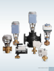
599 Series Ball Valves Stainless Steel or Chrome Trim Meets Specifications for More Applications! With better sizing, superior long-life reliability, and economical pricing, our complete range of ball valves with chrome or stainless steel trim choices are designed to provide excellent equal percentage flow control and so much more.
Two- and Three-Way Ball Valves 1/2 to 2“, Equal Percentage Flow Normally Open or Normally Closed 600 WOG/ANSI Class 250 Description Specifications Designed to provide excellent equal percentage flow control, Ball Valves are available in 1/2 to 2-inch line sizes and are 1/4-turn rotary control valves. These ball valves are designed to couple with an OpenAir actuator. Static Pressure/Temp. .......................................
599 Series Ball Valves 2-Way Ball Valve and Actuator. 3-Way Ball Valve and Actuator.
Two- and Three-Way Ball Valves 1/2 to 2“, Equal Percentage Flow Normally Open or Normally Closed 600 WOG/ANSI Class 250 2-1/2 in. (60 mm) SERVICE ENVELOPE Two-Way Ball Valves with Actuator Dimensions and Service Envelope 0.5 in. ROUND OR 8 mm SQUARE SHAFT E D SIEMENS TOP VIEW 8 in. (200 mm) SERVICE ENVELOPE END VIEW SIDE VIEW 2-1/2 in. (60 mm) SERVICE ENVELOPE F D B 8 in. (200 mm) SERVICE ENVELOPE Dimensions END VIEW A BValve Size (mm) VE0254R2 Part No.
599 Series Ball Valves 2-1/2 in. (60 mm) SERVICE ENVELOPE 3-Way Ball Valve 2-Way Ball Valve and Actuator. and Actuator. Three-Way Ball Valves with Actuator Dimensions and Service Envelope 0.5 in. ROUND OR 8 mm SQUARE SHAFT E D SIEMENS TOP VIEW 8 in. (200 mm) SERVICE ENVELOPE END VIEW SIDE VIEW 2-1/2 in. (60 mm) SERVICE ENVELOPE F 8 in. (200 mm) SERVICE ENVELOPE 0.5 in. ROUND OR 8 mm SQUARE SHAFT Dimensions END VIEW A 1/2" (15 mm) 3/4" (20 mm) 1 in.
Two-Way Ball Valve Assemblies 1/2 to 3/4“, Equal Percentage Flow Chrome-Plated Brass Ball and Brass Stem or Stainless Steel Ball and Stem Electronic Spring Return Actuator, GQD Series Two-way Ball Valve & Spring Return Actuator Assembly NO/NC 1/2 to 3/4" 2-way Valve Body Part No. Spring Return Actuator Normally Open Valve Size in. Flow Close Rate Off Cv psi Normally Closed 2P Floating 2-10 Vdc 2P Floating 2-10 Vdc GQD121.1P GQD131.1P GQD151.1P GQD121.1P GQD131.1P GQD151.
599 Series Ball Valves Two-Way Ball Valve Assemblies 1 to 2“, Equal Percentage Flow Chrome-Plated Brass Ball and Brass Stem or Stainless Steel Ball and Stem Electronic Spring Return Actuator, GMA Series Two-way Ball Valve & Spring Return Actuator Assembly NO/NC 1 to 2" Spring Return Actuator Normally Open 2-way Valve Body Part No. Valve Size in. Flow Close Rate Off Cv psi Normally Closed 2P Floating 0-10 Vdc 2P Floating 0-10 Vdc GMA121.1P GMA131.1P GMA161.1P GMA121.1P GMA131.1P GMA161.
Two-Way Ball Valve Assemblies Chrome-Plated Brass Ball and Brass Stem Electronic Non-Spring Return Actuator, GDE Series Two-way Ball Valve & Non-spring Return Actuator Assembly NO 1/2 to 1-1/4" 2-way Valve Body Part No. Non-Spring Return Actuator Normally Open Floating Valve Size in. Flow Close Rate Off Cv psi GDE131.1P 3-foot (.9m) Wires 0.4 0.63 1.0 1.6 2.5 4.0 6.3 10 6.
599 Series Ball Valves Two-Way Ball Valve Assemblies Stainless Steel Ball and Stem Electronic Non-Spring Return Actuator, GDE Series Two-way Ball Valve & Non-spring Return Actuator Assembly NO 1/2 to 1-1/4" 2-way Valve Body Part No. Non-Spring Return Actuator Normally Open Floating Valve Size in. Flow Close Rate Off Cv psi GDE131.1P 3-foot (.9m) Wires 0.4 0.63 1.0 1.6 2.5 4.0 6.3 10 6.
Two-Way Ball Valve Assemblies Chrome-Plated Brass Ball and Brass Stem or Stainless Steel Ball and Stem Electronic Non-Spring Return Actuator, GLB Series Two-way Ball Valve & Non-spring Return Actuator Assembly NO/NC 1-1/2 to 2" 2-way Valve Body Part No. Non-Spring Return Actuator Valve Size in. Flow Close Rate Off Normally Open Normally Closed Floating 0-10 Vdc GLB131.1Q Conduit Adapter & 6-foot (1.8m) Wires Cv psi GLB131.1P 3-foot (.
599 Series Ball Valves Three-Way Ball Valve Assemblies Chrome-Plated Brass Ball and Brass Stem Electronic Spring Return Actuator, GMA Series Three-way Ball Valve & Spring Return Actuator Assembly Water Mixing 1/2 to 2" 3-Way Valve Body Part No. Spring Return Actuator Normally Open A-AB Valve Size in. Flow Close Rate Off 2P Floating 0-10 Vdc GMA131.1P Assembly with 3 ft. Wires GMA161.1P Assembly with 3 ft. Wires Cv psi GMA121.1P Assembly with 3 ft. Wires 0.4 0.63 1.0 2.
Three-Way Ball Valve Assemblies Chrome-Plated Brass Ball and Brass Stem Electronic Non-Spring Return Actuator, GDE and GLB Series Three-way Ball Valve & Non-spring Return Actuator Assembly Water Mixing 1/2 to 1-1/4" 3-Way Valve Body Part No. Non-Spring Return Actuator Normally Open Floating Valve Size in. Flow Close Rate Off Cv psi GDE131.1P Assembly with 3 ft. Wires 0.4 0.63 1.0 2.
Magnetic Valves Incredibly fast and accurate positioning; long-life reliability Magnetic valve and actuator assemblies use magnetic actuation to enhance response time and improve stability. A less than two-second positioning time and 1000:1 high-resolution stroke enables extremely fast and accurate positioning. Their unrivaled performance in water or steam HVAC applications make them the right choice for light industrial process control and extremely fast closed loop control.
Control Valves for Hot and Chilled Water Description Specifications The Magnetic MX.. Mixing Valve uses magnetic actuation to enhance response time and provide stability. Large signal changes switch the actuator to the large signal band, allowing high-gain response to quickly position the valve element. Small signal changes switch the actuator to the small signal band to provide loop stability and precise positioning. Operating Voltage.....................................................................
Magnetic Valves MXG461...U Magnetic Control Valve. Dimensions for MX.461...U Valves with Electronic Module Dimensions shown in inches (mm). Part No. MXG461.15-0.6U MXG461.15-1.5U MXG461.15-3.0U MXG461.20-5.0U MXG461.25-8.0U MXG461.32-12U MXG461.40-20U MXG461.50-30U DI 1/2 1/2 1/2 3/4 1 1-1/4 1-1/2 2 DA 1 1 1 1-1/4 1-1/2 2 2-1/4 2-3/4 L 3.15 (80) 3.15 (80) 3.15 (80) 3.74 (95) 4.33 (110) 4.92 (125) 5.51 (140) 6.69 (170) L1 1.67 (42.5) 1.67 (42.5) 1.67 (42.5) 2.07 (52.5) 2.22 (56.5) 2.66 (67.5) 3.
Control Valves for Hot and Chilled Water MX.461...U Flanged Valves with Electronics Module Dimensions Dimensions shown in inches (mm). Part No. MXF461.65-50U 124 L 11.42 (290) L1 4.92 (125) D b k 7.00 (177.8) 0.88 (22.4) 5.50 (139.7) Contact Customer Support at 1-888-593-7876 to order today! d 4X H 0.75 (19.05) 15.43 (392) E 3.15 (80) F 3.94 (100) Weight lb. (kg) 63.1 (28.
Magnetic Valves MXG461...U Magnetic Control Valve. Sizing Part No. MXG461.15-0.6U MXG461.15-1.5U MXG461.15-3.0U MXG461.20-5.0U MXG461.25-8.0U MXG461.32-12U MXG461.40-20U MXG461.50-30U MXF461.65-50U * Line Size (in.) 1/2 1/2 1/2 3/4 1 1-1/4 1-1/2 2 2-1/2 Cv 0.7 1.7 3.5 5.8 9.3 14 23 35 58 Max. Close-off Pressure (psi) 44 44 44 44 44 44 44 44 44 Power for Transformer Sizing (VA) 29 29 29 29 29 29 44 44 46 Power Consumption (W) 5 5 5 5 5 5 6 6 6 Fuse Required (A) 3.15 3.15 3.15 3.15 3.15 3.15 4.00 4.
Control Valves for Hot and Chilled Water with ZM Signal Module Description Specifications The Magnetic M3P..FY valve uses a magnetic actuator to positively position with extremely high speed and accuracy. The combination of >1000:1 resolution and full range positioning in less than one second allows exceptional loop stability and reaction time. Operating Voltage........................................................................... 24 Vac Features Frequency.........................................
Magnetic Valves Magnetic M3P..FY Mixing Valve with Actuator. M3P..FY Control Valve Dimensions Dimensions shown in inches (mm). Part No. L M3P80FY 12.20 (310) M3P100FY 13.78 (350) L1 5.51 (140) 6.30 (160) D 7.87 (200) 8.66 (220) b 0.87 (22) 0.94 (24) k 6.30 (160) 7.09 (180) d 8 x 0.71 (8x18) 8 x 0.71 (8x18) H 20.00 (508) 22.44 (570) E 5.71 (145) 5.71 (145) F 4.88 (124) 4.88 (124) Weight lb. (kg) 100.0 (45.5) 130.0 (59.0) Table Note: Counter flanges are not supplied.
Control Valves for Hot and Chilled Water with ZM Signal Module Sizing Part No. M3P80FY M3P100FY 128 Valve Size (in.) 3 4 Cv 93 152 Max. Differential Pressure and Close-off (psi) 44 29 (bar) 3 2 Power for Transformer Sizing (VA) 80 120 Contact Customer Support at 1-888-593-7876 to order today! Power Consumption (W) 20 30 Wire Gauge (AWG) 14 12 Max. Wiring Length (ft.
Magnetic Valves Magnetic M3P..FY Mixing Valve with Actuator. M3P...FY Valves with ZM Module Product Ordering Description 3" 3-way, Pilot Position 4" 3-way, Pilot Position 3" 2-way, Pilot Position 4" 2-way, Pilot Position 3" 3-way, Pilot Position 4" 3-way, Pilot Position Cv Without Flanges 93 152 With Flanges 93 152 93 152 Part No. M3P80FY M3P100FY M3P80FY/2BN M3P100FY/2BN M3P80FY/3BN M3P100FY/3BN www.usa.siemens.
Modulating Control Valves with Magnetic Actuators Positioning Control and Position Feedback for Hot Water and Steam Description Applications MVF461H Series Modulating Control Valves are control valves with magnetic actuators, for modulating control of hot water, high temperature hot water, and steam. The MVF461H... Control Valves are through-port valves with magnetic actuators. The actuator is equipped with an electronics module for positioning control and position feedback.
Magnetic Valves MVF461H Series Magnetic Control Valve. Specifications Electrical Low-voltage Use Only................................................. Class 2 (SELV, PELV) 24 Vac Operating Voltage.......................................................... 24 Vac +20/-15% Frequency.............................................................................. 45 to 65 Hz Typical Power Consumption.............................................. See SizingTable Standby.............................................
Modulating Control Valves with Magnetic Actuators Positioning Control and Position Feedback for Hot Water and Steam Dimensions Dimensions shown in inches (mm). Part No. DN MVF461H15-0.6 15 MVF461H15-1.5 15 MVF461H15-3 15 MVF461H20-5 20 MVF461H25-8 25 MVF461H32-12 32 MVF461H40-20 40 MVF461H50-30 50 L 5.12 (130) 5.12 (130) 5.12 (130) 5.91 (150) 6.30 (160) 7.09 (180) 7.87 (200) 9.05 (230) D 3.74 (95) 3.74 (95) 3.74 (95) 4.13 (105) 4.53 (115) 5.51 (140) 5.91 (150) 6.50 (165) D2 0.16 x 0.55 0.16 x 0.55 0.
Magnetic Valves MVF461H Series Magnetic Control Valve. Sizing Part No. MVF461H15-0.6 MVF461H15-1.5 MVF461H15-3 MVF461H20-5 MVF461H25-8 MVF461H32-12 MVF461H40-20 MVF461H50-30 Line Size (in.) 1/2 1/2 1/2 3/4 1 1-1/4 1-1/2 2 Cv 0.7 1.8 3.5 5.9 9.4 14.0 23.3 35.0 Max. Differential Pressure and Close-off (psi) 145 145 145 145 145 145 145 145 Power for Transformer Sizing (VA) 33 33 33 33 33 43 65 65 Power Consumption (W) 15 15 15 15 15 20 20 26 Slow Fuse 3.15 3.15 3.15 3.15 3.15 4 6.3 6.
Modulating Control Valves with Magnetic Actuators Positioning Control and Position Feedback for Domestic Water Description Applications The MXG461B Modulating Control Valve is a control valve with magnetic actuators, for modulating control of domestic water, cold water and hot water systems. The MXG461B... Modulating Control Valves are through-port or mixing valves with magnetic actuators. The actuator is equipped with an electronics module for positioning control and position feedback.
Magnetic Valves MXG461B Series Modulating Control Valve. Specifications Electrical Low-voltage Use Only.................................................... Class 2 (SELV, PELV) Resolution.......................................................................................1:1000 Type of Operation.................................................................. Modulating 24 Vac Operating Voltage.......................................................... 24 Vac +20/-15% Frequency.........................
Modulating Control Valves with Magnetic Actuators Positioning Control and Position Feedback for Domestic Water 3.94 (100) 1.97 (50) F L3 * Rp AB B G L2 A SVAL0233R1 min. 3.94 (100) E H min. Dimensions L1 Dimensions shown in inches (mm). DN Part No. MXG461B15-0.6 MXG461B15-1.5 MXG461B15-3 MXG461B20-5 MXG461B25-8 MXG461B32-12 MXG461B40-20 MXG461B50-30 (mm) 15 15 15 20 25 32 40 50 (in) Rp x Rp x Rp x Rp x Rp 1 Rp 1x Rp 1x Rp 2 G (in) G1B G1B G1B G1xB G1xB G2B G2xB G2xB L1 3.15 (80) 3.
Magnetic Valves MXG461B Series Modulating Control Valve. Sizing Part No. MXG461B15-0.6 MXG461B15-1.5 MXG461B15-3 MXG461B20-5 MXG461B25-8 MXG461B32-12 MXG461B40-20 MXG461B50-30 Valve Size (in.) 1/2 1/2 1/2 3/4 1 1-1/4 1-1/2 2 Cv 0.7 1.8 3.5 5.8 9.3 14 23 35 Max. Differential Power for Power Pressure and Close-off Transformer Sizing Consumption (psi) (bar) (VA) (W) 145 70 33 15 145 70 33 15 145 70 33 15 116 70 33 15 102 40 33 15 87 40 43 20 87 40 43 20 87 40 65 22 Slow Fuse 3.15 3.15 3.15 3.15 3.
Terminal Modules for Magnetic Valves ZM, ZM../A Terminal Modules for Magnetic Valves. Description ZM../A Terminal Modules are signal transducers/power amplifiers. They convert a 0 to 10 Vdc or 4 - 20 mA control signal and a 24 Vac power supply into a 0 to 20 Vdc phase cut signal. Applications ZM../A Terminal Modules are for use with Magnetic Valves only. Specifications Supply Voltage .................................... 24 Vac +15/-10%, Class 2, 50/60 Hz Current Consumption .............................
Resilient Seat Butterfly Valves Tight shut-off for tighter control of energy costs Resilient Seat Butterfly Valves are now available in sizes up to 20-inches. Excellent for isolation applications, two-way and three-way Butterfly Valves provide 2-position (On/Off), floating and modulating control. Three-way Butterfly Valves are available in a variety of configurations. This catalog contains information on sizes 2 through 12-inches. For larger sizes, please contact Customer Care.
Two- & Three-Way Resilient Seat Valve Assemblies Description Applications Available in two-way and three-way arrangements for two-position (On/Off), floating and modulating control, Resilient Seat Butterfly Valve Assemblies provide bubble-tight shutoff for the assemblies’ full-rated pressure. Butterfly Valve assemblies provide excellent flow control of hot water, chilled water, condenser water, and thermal storage systems applications.
Butterfly Valves Three-Way Butterfly Valve with pneumatic actuators tandem mounted. Two-Way Butterfly Valve with pneumatic actuator. Three-Way Butterfly Valve with electronic actuators tandem mounted. Two-Way Butterfly Valve with electronic actuator. Part Number Configuration BV 2W 02 F S2 L O X X Assembly Configuration 2W 2-Way 3W 3-Way Valve Size 02 2-inch 25 2.
Two-Way Resilient Seat Valve Assemblies S2 Series with 20 psi Pneumatic Spring Return Actuators Figure 1 Dimensions — Two-Way Valve Assemblies with Pneumatic Actuators A B C D E F G Face/ Face Tap Size Bolt Circle H H1 J L M # Bolts Actuator Height Actuator Removal Clearance Actuator Width CL Length Stroke Clearance Valve Size Valve Height Body O.D. CL Pipe To Top Plate 2" 8.50" (216 mm) 6.00" (153 mm) 5.31" (135 mm) 1.69" (43 mm) 0.625-11 UNC-2B 4.75" (121 mm) 4 7.
Butterfly Valves Two-Way Butterfly Valve with pneumatic actuator. 2 to 6-inch, 5 and 6-inch (50 psi close off) 5 and 6-inch, 8 to 10-inch (50 psi close off) 12-inch (50 psi close off) J J J L L L D D M M D M H C A H H E F G B C A E F G C A E F G B B www.usa.siemens.
Three-Way Resilient Seat Valve Assemblies S2 Series with 20 psi Pneumatic Spring Return Actuators Figure 2 Dimensions — Three-Way Valve Assemblies with Pneumatic Actuators A Valve Size Valve Height B C Body O.D. CL Pipe To Top Plate D Face/ Face E Tap Size F Bolt Circle G H H1 J Actuator # Actuator Removal Actuator Bolts Height Clearance Width L M Stroke CL Length Clearance N P Tee Width Run Length Notes 2" 8.50" 6.00" 5.31" (216 mm) (153 mm) (135 mm) 1.69" (43 mm) 0.625-11 4.
Butterfly Valves L J N M Three-Way Butterfly Valve with pneumatic actuators tandem mounted. D 2 to 3-inch L H L J C J BN A N M M E F G D D P 4 to 6-inch H L J C J C A L H B N M M E F G D B A E F G D P P 6 to 12-inch N L H H J C A B M C N B A E F G DE F G P P Drawings shown are for Assemblies A & B. For Assemblies C & D, the valve and actuator are on right-hand side of the run of tee and for Assemblies E & F, the valves are on both sides of the run tee.
Two-Way Resilient Seat Valve Assemblies G Series Electronic with Spring Return and Non-Spring Return Actuators Figure 3 Dimensions — Two-Way OpenAir Electronic Actuator Valve Assemblies A B C D E F G Face/ Face Tap Size Bolt Circle # Bolts H J K L Actuator Dual Actuator Removal Actuator Height Clearance Height H1 H2 Actuator Width Actuator Length CL Length Valve Size Valve Height Body O.D. CL Pipe To Top Plate 2" 8.5" (216 mm) 6" (153 mm) 5.31" (135 mm) 1.69" (43 mm) 0.
Butterfly Valves Two-Way Butterfly Valve with electronic actuator. Minimum Clearance Required For Actuator Removal Minimum Clearance Required For Actuator Removal www.usa.siemens.
Three-Way Resilient Seat Valve Assemblies G Series Electronic with Spring Return and Non-Spring Return Actuators Figure 4 Dimensions — Three-Way OpenAir Electronic Actuator Valve Assemblies A B C D E F G Face/ Face Tap Size Bolt Circle # Bolts H H1 H2 J K L M Actuator Length CL Length Arm Stroke Clearance Valve Size Valve Height Body O.D. CL Pipe To Top Plate 2" 8.50" (216 mm) 6.00" (153 mm) 5.31" (135 mm) 1.69" (43 mm) 0.625-11 UNC-2B 4.75" (121 mm) 4 3.25" (83 mm) 5.
Butterfly Valves Three-Way Butterfly Valve with electronic actuators tandem mounted. Minimum Allowable Clearance For Arm Stroke Minimum Allowable Clearance For Arm Stroke Minimum Clearance Required For Actuator Removal Minimum Clearance Required For Actuator Removal Drawings shown are for Assemblies A & B. For Assemblies C & D, the valve and actuator are on the left-hand side of the run of tee and for Assemblies E & F, the valves are on both sides of the run tee. www.usa.siemens.
Two-Way Resilient Seat Valve Assemblies Electronic Two-Position and Modulating Valve Assemblies Figure 5 Dimensions — Two-Way EPI2 Electronic Actuator Valve Assemblies A B C D E F G H J K Pipe CL To H.W. H.W. D.A. Valve CL To aH.W. Ring Total Width Actuator Model Notes Valve Size Valve Height Body O.D. CL Pipe To Top Plate Face/ Face Actuator Height Actuator Removal Clearance 2" 8.50" (216 mm) 6.00" (153 mm) 5.31" (135 mm) 1.69" (43 mm) 7.75" (196 mm) 6.38" (162 mm) 4.
Butterfly Valves Two-Way Butterfly Valve with electronic actuator. www.usa.siemens.
Three-Way Resilient Seat Valve Assemblies Electronic Two-Position and Modulating Valve Assemblies Figure 6 Dimensions — Three-Way EPI2 Electronic Actuator Valve Assemblies A B C D Valve Size Valve Height Body O.D. CL Pipe To Top Plate Face/ Face 2" 8.50" (216 mm) 8.50" (216 mm) 9.31" (236 mm) 9.31" (236 mm) 10.00" (254 mm) 10.00" (254 mm) 11.38" (289 mm) 11.38" (289 mm) 12.81" (325 mm) 13.94" (354 mm) 13.94" (354 mm) 16.44" (418 mm) 16.19" (411 mm) 19.00" (483 mm) 19.00" (483 mm) 21.
Butterfly Valves Three-Way Butterfly Valve with electronic actuators tandem mounted. Drawings shown are for Assemblies A & B. For Assemblies C & D, the valve and actuator are on the right-hand side of the run of tee and for Assemblies E & F, the valves are on both sides of the run tee. www.usa.siemens.
Two-Way Butterfly Valves 2 to 12" Pneumatic, Spring Return Actuators 2 to 12" Normally Open (Fail Open) 100 psi Close-off — 4-6 150 psi Close-off 50 psi Close-off — 8-12 Normally Closed (Fail Closed) 100 psi Close-off — 4-6 150 psi Close-off 50 psi Close-off — 8-12 Valve Size Flow Rate Part No. Part No.
Butterfly Valves Three-Way Butterfly Valves 2 to 12" Pneumatic, Spring Return Actuators 2 to 12" Valve Size in. Normally Open (Fail Open to Port B) 100 psi Close-off — 4-6 150 psi Close-off 50 psi Close-off — 8-12 Cv Run Branch Part No. Part No. Assembly A Normally Closed (Fail Closed to Port B) 100 psi Close-off — 4-6 150 psi Close-off 50 psi Close-off — 8-12 Part No. Part No.
Three-Way Butterfly Actuators 2 to 12" Pneumatic, Spring Return 2 to 12" Valve Size in. Normally Open (Fail Open to Port B) 100 psi Close-off — 4-6 150 psi Close-off 50 psi Close-off — 8-12 Cv Run Branch Part No. Part No. Assembly A Normally Closed (Fail Closed to Port B) 100 psi Close-off — 4-6 150 psi Close-off 50 psi Close-off — 8-12 Part No. Part No.
Butterfly Valves Two-Way Butterfly Actuators 2 to 4" Electronic, Spring Return 2 to 4" Normally Open Normally Closed 100 psi Close-off 100 psi Close-off Part No. Valve Size Flow Rate Part No.
Three-Way Butterfly Actuators 2 to 4" Electronic, Spring Return 2 to 4" Valve Size in. Normally Open (Fail Open to Port B) Cv Run Branch Normally Closed (Fail Closed to Port B) 100 psi Close-off 100 psi Close-off 100 psi Close-off 100 psi Close-off Part No. Part No. Part No. Part No.
Butterfly Valves Two-Way Butterfly Actuators 2 to 12" Electronic, Non-Spring Return 2 to 12" Non-Spring Return Actuator 150 psi Close-off 100 psi Close-off 50 psi Close-off, 4-6" 100 psi Close-off, 8-12" Part No. Part No. Valve Size Flow Rate Part No.
Three-Way Butterfly Actuators 2 to 12" Electronic, Non-Spring Return 2 to 12" Valve Size in. Normally Open (Fail Open) 100 psi Close-off, 2-6" 150 psi Close-off 50 psi Close-off, 8-12" Cv Run Branch Part No.
Butterfly Valves Three-Way Butterfly Actuators 2 to 12" Electronic, Non-Spring Return 2 to 12" Valve Size in. Normally Open 100 psi Close-off, 2-6" 150 psi Close-off 50 psi Close-off, 8-12" Cv Run Branch Part No.
Contact Customer Support at 1-888-593-7876 to order today!
Resilient Seat Butterfly Valves Tight shut-off for tighter control of energy costs Resilient Seat Butterfly Valves are now available in sizes up to 20-inches. Excellent for isolation applications, two-way and three-way Butterfly Valves provide 2-position (On/Off), floating and modulating control. Three-way Butterfly Valves are available in a variety of configurations. This catalog contains information on sizes 2 through 12-inches. For larger sizes, please contact Customer Care.
Two- & Three-Way Resilient Seat Valve Assemblies Description Applications Available in two-way and three-way arrangements for two-position (On/Off), floating and modulating control, Resilient Seat Butterfly Valve Assemblies provide bubble-tight shutoff for the assemblies’ full-rated pressure. Butterfly Valve assemblies provide excellent flow control of hot water, chilled water, condenser water, and thermal storage systems applications.
Butterfly Valves Three-Way Butterfly Valve with pneumatic actuators tandem mounted. Two-Way Butterfly Valve with pneumatic actuator. Three-Way Butterfly Valve with electronic actuators tandem mounted. Two-Way Butterfly Valve with electronic actuator. Part Number Configuration BV 2W 02 F S2 L O X X Assembly Configuration 2W 2-Way 3W 3-Way Valve Size 02 2-inch 25 2.
Two-Way Resilient Seat Valve Assemblies S2 Series with 20 psi Pneumatic Spring Return Actuators Figure 1 Dimensions — Two-Way Valve Assemblies with Pneumatic Actuators A B C D E F G Face/ Face Tap Size Bolt Circle H H1 J L M # Bolts Actuator Height Actuator Removal Clearance Actuator Width CL Length Stroke Clearance Valve Size Valve Height Body O.D. CL Pipe To Top Plate 2" 8.50" (216 mm) 6.00" (153 mm) 5.31" (135 mm) 1.69" (43 mm) 0.625-11 UNC-2B 4.75" (121 mm) 4 7.
Butterfly Valves Two-Way Butterfly Valve with pneumatic actuator. 2 to 6-inch, 5 and 6-inch (50 psi close off) 5 and 6-inch, 8 to 10-inch (50 psi close off) 12-inch (50 psi close off) J J J L L L D D M M D M H C A H H E F G B C A E F G C A E F G B B www.usa.siemens.
Three-Way Resilient Seat Valve Assemblies S2 Series with 20 psi Pneumatic Spring Return Actuators Figure 2 Dimensions — Three-Way Valve Assemblies with Pneumatic Actuators A Valve Size Valve Height B C Body O.D. CL Pipe To Top Plate D Face/ Face E Tap Size F Bolt Circle G H H1 J Actuator # Actuator Removal Actuator Bolts Height Clearance Width L M Stroke CL Length Clearance N P Tee Width Run Length Notes 2" 8.50" 6.00" 5.31" (216 mm) (153 mm) (135 mm) 1.69" (43 mm) 0.625-11 4.
Butterfly Valves L J N M Three-Way Butterfly Valve with pneumatic actuators tandem mounted. D 2 to 3-inch L H L J C J BN A N M M E F G D D P 4 to 6-inch H L J C J C A L H B N M M E F G D B A E F G D P P 8 to 12-inch N L H H J C A B M C N B A E F G DE F G P P Drawings shown are for Assemblies A & B. For Assemblies C & D, the valve and actuator are on right-hand side of the run of tee and for Assemblies E & F, the valves are on both sides of the run tee.
Two-Way Resilient Seat Valve Assemblies G Series Electronic with Spring Return and Non-Spring Return Actuators Figure 3 Dimensions — Two-Way OpenAir Electronic Actuator Valve Assemblies A B C D E F G Face/ Face Tap Size Bolt Circle # Bolts H J K L Actuator Dual Actuator Removal Actuator Height Clearance Height H1 H2 Actuator Width Actuator Length CL Length Valve Size Valve Height Body O.D. CL Pipe To Top Plate 2" 8.5" (216 mm) 6" (153 mm) 5.31" (135 mm) 1.69" (43 mm) 0.
Butterfly Valves Two-Way Butterfly Valve with electronic actuator. Minimum Clearance Required For Actuator Removal Minimum Clearance Required For Actuator Removal www.usa.siemens.
Three-Way Resilient Seat Valve Assemblies G Series Electronic with Spring Return and Non-Spring Return Actuators Figure 4 Dimensions — Three-Way OpenAir Electronic Actuator Valve Assemblies A B C D E F G Face/ Face Tap Size Bolt Circle # Bolts H H1 H2 J K L M Actuator Length CL Length Arm Stroke Clearance Valve Size Valve Height Body O.D. CL Pipe To Top Plate 2" 8.50" (216 mm) 6.00" (153 mm) 5.31" (135 mm) 1.69" (43 mm) 0.625-11 UNC-2B 4.75" (121 mm) 4 3.25" (83 mm) 5.
Butterfly Valves Three-Way Butterfly Valve with electronic actuators tandem mounted. Minimum Allowable Clearance For Arm Stroke Minimum Allowable Clearance For Arm Stroke Minimum Clearance Required For Actuator Removal Minimum Clearance Required For Actuator Removal Drawings shown are for Assemblies A & B. For Assemblies C & D, the valve and actuator are on the left-hand side of the run of tee and for Assemblies E & F, the valves are on both sides of the run tee. www.usa.siemens.
Two-Way Resilient Seat Valve Assemblies Electronic Two-Position and Modulating Valve Assemblies Figure 5 Dimensions — Two-Way EPI2 Electronic Actuator Valve Assemblies A B C D E F G H J K Pipe CL To H.W. H.W. D.A. Valve CL To aH.W. Ring Total Width Actuator Model Notes Valve Size Valve Height Body O.D. CL Pipe To Top Plate Face/ Face Actuator Height Actuator Removal Clearance 2" 8.50" (216 mm) 6.00" (153 mm) 5.31" (135 mm) 1.69" (43 mm) 7.75" (196 mm) 6.38" (162 mm) 4.
Butterfly Valves Two-Way Butterfly Valve with electronic actuator. www.usa.siemens.
Three-Way Resilient Seat Valve Assemblies Electronic Two-Position and Modulating Valve Assemblies Figure 6 Dimensions — Three-Way EPI2 Electronic Actuator Valve Assemblies A B C D Valve Size Valve Height Body O.D. CL Pipe To Top Plate Face/ Face 2" 8.50" (216 mm) 8.50" (216 mm) 9.31" (236 mm) 9.31" (236 mm) 10.00" (254 mm) 10.00" (254 mm) 11.38" (289 mm) 11.38" (289 mm) 12.81" (325 mm) 13.94" (354 mm) 13.94" (354 mm) 16.44" (418 mm) 16.19" (411 mm) 19.00" (483 mm) 19.00" (483 mm) 21.
Butterfly Valves Three-Way Butterfly Valve with electronic actuators tandem mounted. Drawings shown are for Assemblies A & B. For Assemblies C & D, the valve and actuator are on the right-hand side of the run of tee and for Assemblies E & F, the valves are on both sides of the run tee. www.usa.siemens.
Two-Way Butterfly Valves 2 to 12" Pneumatic, Spring Return Actuators 2 to 12" Normally Open (Fail Open) 100 psi Close-off — 4-6 150 psi Close-off 50 psi Close-off — 8-12 Normally Closed (Fail Closed) 100 psi Close-off — 4-6 150 psi Close-off 50 psi Close-off — 8-12 Valve Size Flow Rate Part No. Part No.
Butterfly Valves Three-Way Butterfly Valves 2 to 12" Pneumatic, Spring Return Actuators 2 to 12" Valve Size in. Normally Open (Fail Open to Port B) 100 psi Close-off — 4-6 150 psi Close-off 50 psi Close-off — 8-12 Cv Run Branch Part No. Part No. Assembly A Normally Closed (Fail Closed to Port B) 100 psi Close-off — 4-6 150 psi Close-off 50 psi Close-off — 8-12 Part No. Part No.
Three-Way Butterfly Actuators 2 to 12" Pneumatic, Spring Return 2 to 12" Valve Size in. Normally Open (Fail Open to Port B) 100 psi Close-off — 4-6 150 psi Close-off 50 psi Close-off — 8-12 Cv Run Branch Part No. Part No. Assembly A Normally Closed (Fail Closed to Port B) 100 psi Close-off — 4-6 150 psi Close-off 50 psi Close-off — 8-12 Part No. Part No.
Butterfly Valves Two-Way Butterfly Actuators 2 to 4" Electronic, Spring Return 2 to 4" Normally Open Normally Closed 100 psi Close-off 100 psi Close-off Part No. Valve Size Flow Rate Part No.
Three-Way Butterfly Actuators 2 to 4" Electronic, Spring Return 2 to 4" Valve Size in. Normally Open (Fail Open to Port B) Cv Run Branch Normally Closed (Fail Closed to Port B) 100 psi Close-off 100 psi Close-off 100 psi Close-off 100 psi Close-off Part No. Part No. Part No. Part No.
Butterfly Valves Two-Way Butterfly Actuators 2 to 12" Electronic, Non-Spring Return 2 to 12" Non-Spring Return Actuator 150 psi Close-off 100 psi Close-off 50 psi Close-off, 4-6" 100 psi Close-off, 8-12" Part No. Part No. Valve Size Flow Rate Part No.
Three-Way Butterfly Actuators 2 to 12" Electronic, Non-Spring Return 2 to 12" Valve Size in. Normally Open (Fail Open) 100 psi Close-off, 2-6" 150 psi Close-off 50 psi Close-off, 8-12" Cv Run Branch Part No.
Butterfly Valves Three-Way Butterfly Actuators 2 to 12" Electronic, Non-Spring Return 2 to 12" Valve Size in. Normally Open 100 psi Close-off, 2-6" 150 psi Close-off 50 psi Close-off, 8-12" Cv Run Branch Part No.
162 Contact Customer Support at 1-888-593-7876 to order today!
Accessories & Service Kits Featured Accessory Universal Valve Retrofit Kit Description The Universal Valve Retrofit Kit allows you to install a state-of-theart Siemens Flowrite Electronic Actuators, regardless of the valve’s manufacturer. This kit contains the parts needed to adapt a valve to all Flowrite Pneumatic or SKB, SKC, SKD or SAX Actuators. Kit includes: bonnet adapter, bonnet adapter insert, stem adapter jam nut and square head set screws.
Description Product Group Quantity Part No. Actuator Support Ring. All Zone Valves Package of 10 599-00599 Weathershield for Zone & Powermite Valves. All Zone Valves & Powermite Valves 1 599-10077 Adapter for 1/2" Conduit. SQS 1 544-023 Conduit Connectors. SSA SSP SSB 1 ASY97 Terminal Plug and Cover. Labeled Y1-G-Y2. (Cover not shown) SSB81U SSA/P81U 1 ASY99 Terminal Plug and Cover. Labeled G-G0-Y. (Cover not shown) SSB61U SSA/SSP61U 1 ASY100 Replacement Screws.
Accessories & Service Kits Description Product Group Quantity Part No. SSC 1 411555648 All Zone Valves & Powermite Valves 1 599-10077 1 599-10078 1 ASC1.6 1 ASC9.3BCU 1 ASC9.3DU 1 ASC10.51 • 1000 Ω 1 ASZ7.5/1000 • 200 Ω 1 ASZ7.5/200 1 ASZ7.5/135 1 AZX61.1 Powermite Valves Service Kit. Includes terminal cover, cover screws (2), tail piece and screw, cable lock and terminal blocks (3). (current model) Weathershield for Zone & Powermite Valves.
Description Product Group Quantity Part No. • 8-inch 1 599-00426 • 12-inch 1 599-00423 Flowrite Valves Positioning Relay and Mounting Kit. Adapter for 1/2" Conduit. SKD & SKB/C 1 544-023 Rack and Pinion/Bracket Only. Use with OpenAir on Flowrite 1/2-2" (20 mm) stroke valves. Flowrite 1 599-03610 Weathershield. SKB/SKC 1 599-10065 Weathershield. SKD/SQX 1 599-10071 Weathershield. SAX 1 ASK39.1 SKB/SKC, SKD, SQX 1 See table below Universal Valve Retrofit Kit.
Product Group Quantity Part No. Flowrite 1 See table below Accessories & Service Kits Description Flowrite 1/2" to 2" 2-way Bronze Valve Body Rebuild/Repack Service Kits.
Continued… Description Product Group Quantity Part No. Flowrite 1 See table below Flowrite 1/2 to 2" 2-way Bronze Valve Body Rebuild/Repack Service Kits. FxF 599-03126 599-03127 599-03128 599-03129 599-03130 599-03131 599-03132 599-03133 599-03134 599-03162 599-03163 599-03164 599-03165 599-03166 599-03167 599-03168 599-03169 599-03170 599-03180 599-03181 599-03182 599-03183 599-03184 599-03185 599-03186 599-03187 599-03188 Valve Part No.
Product Group Quantity Part No. Flowrite 1 See table below Accessories & Service Kits Description Flowrite 2-1/2 to 6" 2-way Flanged Iron Valve Body Rebuild/Repack Service Kits. Valve Part No.
Continued… Description Product Group Quantity Part No. Flowrite 1 See table below Flowrite 2-1/2 to 6" 2-way Flanged Iron Valve Body Rebuild/Repack Service Kits. Valve Part No. 599-06120 599-06121 599-06122 599-06123 599-06124 599-06130 599-06131 599-06132 599-06133 599-06134 599-06140 599-06141 599-06142 599-06143 599-06144 599-06150 599-06151 599-06152 599-06153 599-06154 2-1/2 to 6" 3-way Flanged Iron Valve Body Rebuild/Repack Service Kit. Flowrite Valve Part No.
Product Group Quantity Part No. Flowrite 1 See table below Accessories & Service Kits Description Flowrite 2-1/2 to 6" High Close Off Rebuild/Repack Service Kits (ANSI 125 & 250) Action Normally Open Normally Closed Valve Body 599-06610 599-06611 599-06612 599-06613 599-06614 599-06615 599-06616 599-06617 599-06618 599-06619 Valve Size Inch (mm) 2-1/2 (65) 3 (80) 4 (100) 5 (125) 6 (150) 2-1/2 (65) 3 (80) 4 (100) 5 (125) 6 (150) 2-1/2 to 6" Flanged Iron Valve Body Repack Kit (14 mm dia.).
Description Product Group Quantity Part No. SKD 1 410456348 SKB/SKC 1 410455828 Flowrite Plastic Wiring Compartment Cover. Manual Override Crank Assembly. SKB/C 1 426855108 SKD 1 426855048 Packing Heating Element. SKB/C 1 599-00418 Packing Heating Element. SKD 1 599-00417 Stem Heater SAX 1 ASZ6.6 Stroke Inverter. 1/2" - 2.5" valves with .75" max. stroke.
Product Group Lower Seat Tools for Valve Size: Flowrite Quantity Part No. Part No. 1 599-09144 — Accessories & Service Kits Description Flowrite • 2-1/2" • 3" 1 599-09145 — • 4" 1 599-09146 — • 5" 1 599-09147 — • 6" 1 599-09148 — Female Male 1 599-09185 599-09181 Flowrite Union Kits.
Description Product Group Quantity Part No. 1 Z205/15 Magnetic 580 PSI Weld Neck Adaptor Flange. MX../M3P/MV.. • 1/2" • 3/4" 1 Z205/20 • 1" 1 Z205/25 • 1-1/4" 1 Z205/32 • 1-1/2" 1 Z205/40 • 2" 1 Z205/50 • 2-1/2" 1 Z205/65 • 3" 1 Z205/80 1 Z205/100 1 Z56/100 • 1/2" 1 Z206/15 • 3/4" 1 Z206/20 • 1" 1 Z206/25 • 1-1/4" 1 Z206/32 • 1-1/2" 1 Z206/40 • 4" 230 PSI Weld Neck Adaptor Flange. MX../M3P • 4" 580 PSI NPT Adaptor Flange. MX../M3P/MV..
Valve Reference Control Valve Sizing and Selection Selecting Globe and Ball Valves The control valve is the most important single element in any fluid handling system, because it regulates the flow of fluid to the process. To properly select a control valve, a general knowledge of the process and components is usually necessary. This reference section can help you select and size the control valve that most closely matches the process requirements.
Control Valve Sizing and Selection Sizing Valves Pressure Drop for Water Flow Pressure Drop for Steam A pressure drop must exist across a control valve if flow is to occur. The greater the drop, the greater the flow at any fixed opening. The pressure drop across a valve also varies with plug position — from minimum when fully open, to 100% of the system drop when fully closed.
Valve Reference Recommended Pressure Drops for Valve Sizing — Steam Valve Sizing and Selection Example 1. With gravity flow condensate removal and inlet pressure less than 15 psi, use a pressure drop equal to the inlet gauge pressure. Select a valve to control a chilled water coil that must have a flow of 35 GPM with a valve differential pressure (∆P) of 5 psi. 2. With vacuum return system up to 7" Hg vacuum and an inlet pressure less than 2 psi, a pressure drop of 2 psi should be used.
Control Valve Sizing and Selection Valve Body Rating The temperature-pressure ratings for ANSI Classes 125 and 250 valve bodies made of bronze or cast iron are shown below. Pressure Description Bronze Screwed Bodies Specification #B16.15-1978 ANSI Amer. Std.; USA; ASME Cast Iron Flanged Bodies Class B-sizes 1 to 12 Specification #B16.1 1975 ANSI Amer. Std.
Valve Reference Valve Sizing Formulas The following definitions apply in the following formulas: Cv Valve flow coefficient, U.S. GPM with P = 1 psi P1 Inlet pressure at maximum flow, psia (abs.) P2 Outlet pressure at maximum flow, psia (abs.) P1 — P2 at maximum flow, psi Q Fluid flow, U.S. GPM Qa Air or gas flow, standard cubic feet per hour (SCFH) at 14.7 psi and 60°F W Steam flow, pounds per hour (lb./hr.
Control Valve Sizing Formulas and Tables Viscosity Factors Specific Gravity of Water The relationship between kinematic and absolute viscosity: Centistoke = Temp T (°F) Absolute Pressure Specific Gravity — S (W=62.4 lb./ft.3 @ 60°F) 60 — 1.000 1.000 100 — 0.993 0.999 Cv Correction Factors 150 — 0.981 0.985 200 — 0.963 0.981 30 0.942 0.971 Centipoise Specific Gravity Saybolt* Univ.
Valve Reference Water Capacity Graph for Zone Valves 400 300 200 80 90 100 70 60 50 40 30 20 8 9 10 Differential Pressure Δ p (kPa) 60 50 40 30 100 80 20 10 8 .0 ) Cv = 7 1" (25 = 4.1 (20) Cv ), 3/4" 5 (1 1/2" = 2.5 (15) Cv " 2 / 1 30 25 20 16 10 8 6 5 4 1/2" 3 6 5 4 3 2 .0 =1 (15) Cv 1 0.8 0.6 0.5 0.4 2 0.3 1 0.8 0.2 0.6 0.5 0.4 0.1 0.08 0.06 0.05 0.3 0.2 0.04 0.03 70 60 50 40 30 20 8 9 10 7 6 5 4 3 2 1 0.
Control Valve Sizing and Selection Water Capacity Tables for Zone Valves Valve Size Inches 1/2 1/2 1/2 1 Cv\1 1.0 2.5 4.1 7.0 2 1.4 3.5 5.7 9.9 3 1.7 4.3 7.1 12.1 4 2.0 5.0 8.2 14.0 5 2.2 5.6 9.2 15.6 Pressure Differential — psi English (AB→A) 6 8 10 15 20 25 2.4 2.8 3.2 3.9 4.4 5.0 6.1 7.1 7.9 9.7 11.2 12.5 10.0 11.6 13.0 15.9 18.3 20.5 17.1 19.8 22.1 27.1 31.3 35.0 30 5.5 13.7 22.4 38.3 40 6.3 15.8 25.9 44.3 50 7.1 17.7 29.0 49.5 60 7.7 19.4 31.8 54.2 75 8.7 22.0 35.5 60.
Valve Reference Water Capacity Graph for Globe Valves For more precise Valve Sizing, use the Water Capacity tables on the next page. www.usa.siemens.
Control Valve Sizing and Selection Water Capacity Tables for Globe Valves Valve Size Inches 1/2" 1/2" 1/2" 1/2" 1/2" 1/2" 3/4" 1" 1-1/4" 1-1/2" 2" 2-1/2" 3" 4" 5" 6" Cv\1 0.4 0.63 1.0 1.6 2.5 4 6.3 10 16 25 40 63 100 160 250 400 2 psi 0.6 0.9 1.4 2.3 3.5 5.7 8.9 14.1 23 35 57 89 141 226 354 566 3 psi 0.7 1.1 1.7 2.8 4.3 7 10.9 17.3 28 43 69 109 173 277 433 693 4 psi 0.8 1.3 2.0 3.2 5.0 8.0 12.6 20 32 50 80 126 200 320 500 800 5 psi 0.9 1.4 2.2 3.6 5.6 8.9 14.1 22 36 56 89 141 224 358 559 894 6 psi 1.
Valve Reference Maximum Steam Capacity at Various Pressure Differentials for Globe Valves 2 psi Valve Size Inches 1/2" 1/2" 1/2" 1/2" 1/2" 1/2" 3/4" 1" 1-1/4" 1-1/2" 2" 2-1/2" 3" 4" 5" 6" Cv 0.4 0.63 1 1.6 2.5 4 6.3 10 16 25 40 63 100 160 250 400 1 psi 4.78 7.53 12 19 30 48 75 120 191 299 478 753 1195 1913 2988 4781 2 psi 6.66 11 17 27 42 67 105 166 266 416 666 1048 1664 2663 4160 6657 3 psi 8.
Control Valve Sizing and Selection Globe Valve Close-off Pressures — MZ Series Electronic Valve Size 1/2", Cv ≤ 1.6 1/2", Cv ≤ 4 3/4 to 1", Cv ≤ 10 1/2", Cv ≤ 1.
Valve Reference Globe Valve Close-off Pressures — Pneumatic Spring Range 3 to 8 psi (21 to 55 kPa) 8" Actuator 4" Actuator Valve Size in.
Control Valve Sizing and Selection Close-off Pressures for Electronic Globe Valves Valve Size in.
Valve Reference Close-off Pressures for Electronic Ball Valves 2-Way Valve Body Part No.
Control Valve Sizing and Selection Flow Coefficients for 2-Way, Full-Port (no flow optimizer) Ball Valves in. Valve Size (mm) Valve Part No. 1/2 (15) 599-10307 or 599-10307S 3/4 (20) 599-10311 or 599-10311S 1 (25) 599-10316 or 599-10316S 1-1/4 (30) 599-10321 or 599-10321S 1-1/2 (40) 599-10326 or 599-10326S 2 (50) 599-10329 or 599-10329S 1/2 (13) 10.0 3/4 (20) 6.94 (8.62) (5.93) Effective (Installed) Cv (Kvs) Supply Line Size in Inches (mm) 1 1-1/4 1-1/2 2 (25) (32) (38) (51) 6.
Valve Reference Dimensions for Cast Iron Flanges 2-1/2 to 8-inch Cast Iron Flange Dimensions (as defined by ANSI standard B16.1) ANSI Class 125. ANSI Class 250.
Control Valve Sizing and Selection Steam Saturation Pressure / Temperature Table Vacuum Inches Hg 29.74 29.67 29.56 29.40 29.18 28.89 28.50 28.00 27.88 25.85 23.81 21.78 19.74 17.70 15.67 13.63 11.60 9.56 7.52 5.49 3.45 1.42 Absolute Pressure psi 0.0886 0.1217 0.1780 0.2562 0.3626 0.505 0.696 0.946 1 2 3 4 5 6 7 8 9 10 11 12 13 14 Temperature degrees Fahrenheit 32 40 50 60 70 80 90 100.00 101.83 126.15 141.52 153.01 162.28 170.06 176.85 182.86 188.27 193.22 197.75 201.96 205.87 209.
Valve Reference Butterfly Valve Selection and Sizing Introduction When selecting a butterfly valve for water applications you must first determine the requirements of the valve assembly.
Butterfly Valve Selection and Sizing 3- way Flow Coefficients (Cvs) Degrees Open 0° 10° 20° 30° 40° 50° 60° 70° 80° 90° 90° 80° 70° 60° 50° 40° 30° 20° 10° 0° 2" 54 53 49 43 38 40 44 52 57 58 2-1/2" 114 108 93 74 52 64 78 102 126 135 3" 188 178 148 114 55 95 120 165 210 229 4" 385 374 348 313 150 295 345 419 482 511 5" 642 627 600 563 270 549 630 740 829 870 6" 935 909 867 809 483 780 895 1051 1180 1242 8" 1688 1573 142
Note: 3-way Cvs have already been adjusted. Adjusted Cvs for Piping Geometry Factors Pipe Size Size 2-1/2" 3" 2" 47 38 2-1/2" 3" 4" 5" 6" 8" 10" 12" 14" 16" 18" 4" 125 5" 6" 8" 10" 12" 14" 16" 18" 20" 22" 24" 79 189 149 505 408 947 685 1138 916 2256 1822 3812 3123 5747 4811 8900 7600 11830 10140 16560 20" 14580 20460 18260 6-inch 3-way Assembly at Constant Valve Differential Pressure (corrected for tee loss) www.usa.siemens.com/hvac 195 Valve Reference 3.
Terminology Absolute Pressure — Absolute pressure is referenced to a theoretical perfect vacuum. At standard atmospheric pressure, absolute pressure may be calculated by adding 14.7 psi to the observed gauge pressure. Design Conditions — The assumed environmental variables that define the performance limits required of a HVAC system. This may include maximum and minimum outside air temperatures, expected solar and other thermal loads, occupancy levels, etc.
Flow Coefficient — The flow coefficient is the constant that relates volumetric flow, differential pressure, and specific gravity of a fluid through a metering device. Cv is the flow coefficient in imperial units. For liquids through a standard orifice it is calculated to be equal to the volumetric flow in gallons per minute times the square root of the specific gravity divided by the square root of the differential pressure in psi.
Terminology Screwed- end connection — A valve body with a threaded pipe connection, usually female NPT threads, in valve bodies through 2”. Two-way Valve — A valve body with a single flow path — one inlet and one outlet. Seat — The stationary portion of the valve which seals the valve, thus prevents flow, when in full contact with the movable ball, plug or disc. Valve — A control device which will vary the rate of flow of a medium such as water or steam.
Notes www.usa.siemens.
Notes 200 Contact Customer Support at 1-888-593-7876 to order today!
Notes www.usa.siemens.
Notes 202 Contact Customer Support at 1-888-593-7876 to order today!
Terms & Conditions Terms & Conditions Ordering All orders are to be mailed or faxed to: Siemens Industry Inc., Building Technologies Attn: Customer Support 1000 Deerfield Parkway Buffalo Grove, IL 60089-4513 Phone: 888-593-7876 (Fax: 877-765-4295) Orders can be tracked on-line. Contact Customer Support to set up an on-line account. Pricing Policy Prices published herein are List Prices. Net pricing is determined by annual volume. Contact your local Siemens sales representative for your pricing.
Limited Warranty This Limited Warranty applies in the United States and Canada to products manufactured by Siemens or bearing its nameplate (the “Product”). Siemens warrants the Product purchased from it or its authorized reseller to be free from defects in material and workmanship under normal use during the two year warranty period from the date of manufacture.
Increase productivity with the Siemens Online Ordering Webshop! www.usa.siemens.
2012 Valve & Valve Actuator Catalog Siemens Industry, Inc. 1000 Deerfield Parkway Buffalo Grove, IL 60089-4513 USA Tel. 847-215-1000 Siemens Building Technologies, Ltd. 2 Kenview Blvd. Brampton, Ontario L6T 5E4 Canada Tel. 905-799-6649 Ready to place an order? Contractor or Wholesalers, call 1-888-593-7876 Siemens Solution Partners, call 1-800-516-9964 Canadian Customers, call 1-800-236-2967 All other customers, call your local Siemens branch Siemens Online Ordering, go online to www.usa.siemens.