
Technical data


Safety Integrated Functions
8.9 Acceptance test and acceptance report
Function Manual
Function Manual, 06/2012, 6SL3097-4AB10-0BP4
509
Acceptance test for Safe Speed Monitor with encoder (Extended Functions)
Table 8- 41 "Safe Speed Monitor" function
No. Description Status
Initial state
• Drive in the "Ready" state (p0010 = 0)
• Safety Integrated Extended Functions enabled (p9601.2 = 1)
• Safety functions enabled (p9501.0 = 1)
• Safety configured with encoder (p9506 = 0)
1.
• No Safety message (r0945, r2122, r9747); see note "Non-critical alarms" at the
beginning of the section "Acceptance tests".
Switch off the drive or specify speed setpoint = 0
Configure and activate trace recording
• Trigger: Trigger on variable - bit pattern (r9722.15 = 1)
• Record the following values: r9714[0], r9722
• Select the time interval and pretrigger so you can recognize when the level
exceeds the SSM limit (p9346/p9546) and subsequently falls below it again
For better analysis, display the following bit values:
• r9722.15 (SSM (speed below the limit value))
Switch on the drive and specify the setpoint so that the level briefly exceeds the SSM limit and then drops below
it once more
2.
• Check whether the drive is turning
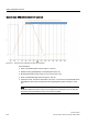
Analyze trace:
• If r9714[0] exceeds the SSM limit p9346/p9546, r9722.15 = 0 applies
• After the limit has been violated, r9722.15 = 1 is valid
3.
• If the hysteresis is active, r9722.15 only becomes 1 again if r9714[0] falls below the
limit p9346/p9546 minus hysteresis value p9347/p9547
4. Save/print the trace and add it to the acceptance report (refer to the example below)