
Technical data


Diagnostics
5.2 Diagnostics via STARTER
Function Manual
Function Manual, 06/2012, 6SL3097-4AB10-0BP4
101
Properties
• Resolution
8-bit
• Voltage range
0 V to +4.98 V
• Measuring cycle
Depends on the measuring signal
(e.g. actual speed value in speed controller cycle 250 μs)
Short-circuit-proof
Parameterizable scaling
Adjustable offset
Adjustable limitation
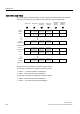
Signal chart for measuring sockets
/LPLWDWLRQ
0HDVXULQJVRFNHW
6FDOLQJ
7KHIROORZLQJDSSOLHVWR
PHDVXULQJGHYLFHV
5L! 0വ
>@!0HDVXULQJVRFNHW7
>@!0HDVXULQJVRFNHW7
1RWH
U>@LQGLFDWHVWKHVFDOLQJSHUYROW
7
7
\
\
[
[
$
'
0
9
S>@9
U>@
S>@
S>@
S>@
9
S>@9
U>@
U>@ U>@
9
\>9@
\>9@
\
\
9
9
;
;
\>9@
3
3
[>@
[>9@
[
>9@
S>@
9
2IIVHW
Figure 5-11 Signal chart for measuring sockets
Which signal can be output via measuring sockets?
The signal to be output via a measuring socket is specified by parameterizing the connector
input p0771[0...1].
Important measuring signals (examples):
r0060 CO: Speed setpoint before speed setpoint filter
r0063 CO: Actual speed value
r0069[0...2] CO: Phase currents actual value
r0075 CO: Field-generating current setpoint
r0076 CO: Field-generating actual current
r0077 CO: Torque-generating current setpoint
r0078 CO: Torque-generating actual current