
Data Sheet for Product


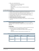

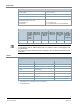


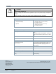
Table Of Contents

5
Siemens Industry, Inc.
A6V11339448
Smart Infrastructure
2021-07-19
Power data
Power supply
Operating voltage AC 24 V -15%/+20%
Frequency 50/60 Hz
Internal fuse 4 A irreversible
Transformer with secondary current limitation of max. 10
A or external secondary current fuse
Non-renewable fuse
Circuit breakers
Max. 10 A, (Class 2, 4A)
Max. 13 A, characteristic B, C, D as per EN 60898
Apparent power (VA) for transformer design
Base load
including
I/O without
load by
field
devices
Max. output
load Triac at
500 mA each
Max. load for
AC 24 V field
supply at
200 mA
Max. load
KNX PL-Link
at 50 mA
Max. load for
DC 24 V field
supply at 100
mA
Power
consumption
including
connected
field devices
DXR2.M10P… 10 4 x 12 = 48 - 4 - 62
NOTE:
To calculate the total VA, add the Base Load + the number of Triacs + field supplies+ KNX
PL-Link devices.
This cannot exceed the maximum power consumption. See the Wiring Guidelines for more
information.
Inputs
Analog Inputs
Resistance sensor Temperature measurement Voltage measurement
AI 1000 Ω AI PT1K 375 (NA)*) AI 0 to 10V
AI 2500 Ω AI PT1K 385 (EU)*) AI 0 to 10V (0 to 100%)
AI 10 KΩ AI (LG-)Ni1000*)
AI 100 KΩ AI Ni1000 DIN*)
AI T1 (PTC)*)
AI NTC10K (Type II)**)
AI NTC100K**)
* A fixed value of 1 Ω is calibrated to correct line resistance.
** Configurable default.