
Application


Room Segment Functions
Device Control Functions HVAC
53
Siemens Industry, Inc.
Application Note
A6V11692042
Smart Infrastructure – Building Products
2019-04-01
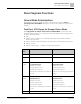
⚫ Selectable duct(s) for ventilation air (one, both, or neither)
⚫ Dedicated outdoor air system (DOAS) support
⚫ Control coordination for extract duct calculation
⚫ Air flow coefficient calculation for air balancing logic (2)
⚫ Interlocks (box coils)
⚫ Supply chain interface (2)
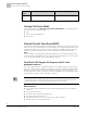
A VAV supply cooling (VavSuCReq), supply heating (VavSuHReq) or ventilation
request (VavSuVntReq) is received from the room control function and processed
into two output signals for VAV supply damper position (VavSuPos1, VavSuPos2).
Basic function: Accept request signal from associated room controller and map it
to appropriate air volume flow setpoint; Compare setpoint to air volume flow in
terminal box; Pass result through a device mode logic switch prior to outputting as
a command to the object that controls the device.
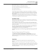
Available status
When the VAV supply damper is available for cooling, heating or ventilation, the
respective binary output signal(s) that indicate availability (VavSuAvlC, VavSuAflH,
VavSuAvlVnt) will be "Yes" (available).
For the ventilation available status to be "Yes", device mode must equal "Control
mode" (modulation). The cooling or heating available status signals additionally
require their respective airflow request signals from the VAV box coil or changeover
signals from the AHU.
The output signal VAV supply airflow provided for ventilation (VavSuAflPvdVnt) is
the amount of airflow available for ventilation. When Supply air VAV available for
ventilation (VavSuAvlVnt) is True, the maximum ventilation value
(VavSuAflMaxVnt) is transferred to VavSuAflPvdVnt.
VavSuAflPvdVnt is the sum of maximal flow (in engineering units) from the supply
VAV boxes. These values are set in each supply VAV for the maximum flow in the
segment.
Dual Duct Supply Airflow PID Controllers
The PID airflow controller (VavSuAirFlCtr1, VavSuAirFlCtr2) compares the
relative air volume flow of the terminal box to the current relative VAV supply
airflow setpoint, and modulates VavSuPos1 or VavSuPos2 as necessary to keep the
box flow at setpoint.
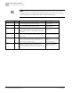
Interlocks
Interlocks are (typically) binary signals that ensure equipment protection.
Additional signals help coordinate the interaction sequences between HVAC
devices.
A signal's direction In / Out (and function, to some degree) depend on the HVAC
device. For example, an airflow status (AirFlSta) interlock signal can be output from
a supply damper or a fan, and sent as input to a coil or an OA damper. In the table
that follows, descriptions of a signal's functionality reflect its usage by the
specified HVAC device.