
User Manual

11
Siemens A6V11393929_en--_c
Smart Infrastructure 2020-09-01
Diagrams
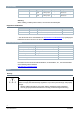
Connection terminals
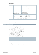
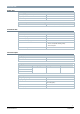
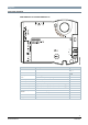
DXR1.M09PDZ-112 and DXR1.M09PDZ-113
Pin Description Terminal
11...13 MS/TP MS/TP connection
, -, +
USB USB interface
81...82 power
24 V~
Power supply AC 24 V V~
System neutral (must always be grounded at the transformer) ⏊
64…66 inputs Universal input X1, X2
62, 63 outputs DC 0…10 V output Y10
54…56 Triac outputs Digital output, switching to phase (AC 24 V) or neutral (⏊) Y3, Y4
57…59 Triac outputs Digital output, switching to phase (AC 24 V) or neutral (⏊) Y5, Y6
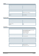
Room unit connection RJ45 interface
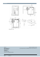
ΔP differential pressure
detector
Connected to the higher pressure P1+
Connected to the lower pressure P1-
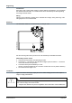
Service Service button SVC
Display Operation LED RUN