
User Manual

Application Sheet
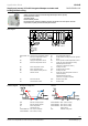
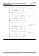
VAV045
Supply and extract VAV with integrated damper actuator and
heating/chilled ceiling
DXR1.E10PL-112
6/24
Technical information in this document are subject to change. Drawings serve illustration purposes only.
Siemens is not responsible for content and any manual modifications.
2020-09-01
A6V11643426_en--_b
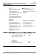
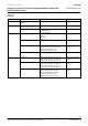
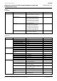
Application
configuration
Equipment
Channel/Signal
Settings example
On-board output
Supply air VAV position (integrated
actuator)
Y1, Y2; 3-position
Y1, Y2; 3-position
On-board input
Supply air VAV differential air
pressure (integrated sensor) (YS)
P1
P1
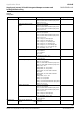
Window contact (D1)
D1; Normally closed
X1; Normally closed
X2; Normally closed
D1; Normally closed
KNX PL-Link devices
Room operator unit device 1
QMX2.P33
QMX2.P43
QMX3.P34
QMX3.P74
QMX3.P74
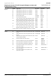
Sensor device 2 (D2)
UP 258D12
UP 258D12
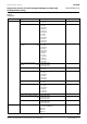
VAV box extract
GDB181.1E/KN; Air volume flow control
GLB181.1E/KN; Air volume flow control
GDB181.1E/KN; Position control
GLB181.1E/KN; Position control
GLB181.1E/KN; Air volume
flow control
Radiant ceiling device
GDB111.9E/KN
GDB111.9E/KN
HVAC
Supply air VAV
Supply air VAV 12, press, duct area, ctr.
Supply air VAV 13, press, flow conv, ctr.
Supply air VAV 15, press, dependent ctrl.
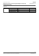
Supply air VAV 13, press,
flow conv, ctr.
Extract air VAV
Extract air VAV 11, external air flow ctr.
Extract air VAV 12, press, duct area, ctr.
Extract air VAV 13, press, flow conv, ctr.
Extract air VAV 15, press.dependent ctr.
Extract air VAV 11, external
air flow ctr.
Radiant ceiling
Chilled ceiling with chilled water 11
Ceiling heat./chilled ceiling 2-pipe 11
Ceiling heat./chilled ceiling 4-pipe 13
Ceiling heating with hot water 11
Ceiling heat./chilled ceiling 4-pipe 15
Ceiling heat./chilled ceiling
4-pipe 15