
User Manual

Application Sheet
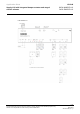
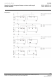
VAV044
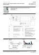
Supply VAV with integrated damper actuator and staged
electric reheater
DXR1.M09PDZ-112
DXR1.E09PDZ-112
8 / 10
Technical information in this document are subject to change. Drawings serve illustration purposes only.
Siemens is not responsible for content and any manual modifications.
2020-09-01
A6V11757331_en--_b
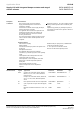
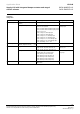
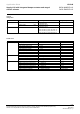
Optional
configuration
Equipment
Channel/Signal
Settings example
On-board output
Extract air VAV position
Y1, Y2; 3-position (integrated actuator)
Y3, Y4; 3-position
Y5, Y6; 3-position
Y10; 0...10 V
Air volume flow; Y10; 0...10 V
Enable heating coil electric position
Y3; Normally open
Y5; Normally open
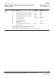
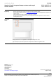
On-board input
Extract air VAV differential air pressure
(B8)
X1; 0...10 V
X2; 0...10 V
P1
Extract air VAV air volume flow
X1; 0...10 V
X2; 0...10 V
Extract air temperature (B3)
X1; Ni1000
X1; 0…10 V
X1; NTC100K
X1; NTC10K
X1; PT1K_EU
X1; PT1K_NA
X2; Ni1000
X2; 0…10 V
X2; NTC100K
X2; NTC10K
X2; PT1K_EU
X2; PT1K_NA
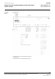
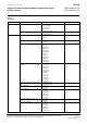
Primary air temperature for air after-
treatment (B1)
X1; Ni1000
X1; 0…10 V
X1; NTC100K
X1; NTC10K
X1; PT1K_EU
X1; PT1K_NA
X2; Ni1000
X2; 0…10 V
X2; NTC100K
X2; NTC10K
X2; PT1K_EU
X2; PT1K_NA
Heating coil over-temperature detection
(D3)
X1; Normally closed
X2; Normally closed
Room air quality (B6)
X1; 0…10 V
X2; 0…10 V
Room temperature (B5)
X1; Ni1000
X1; 0…10 V
X1; NTC100K
X1; NTC10K
X1; PT1K_EU
X1; PT1K_NA
Relative air humidity for room (B7)
X1; 0…10 V
X2; 0…10 V
Supply air temperature (B2)
X2; Ni1000
X2; 0…10 V
X2; NTC100K
X2; NTC10K
X2; PT1K_EU
X2; PT1K_NA