
User Manual

Application Sheet
VAV044
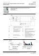
Supply VAV with integrated damper actuator and staged
electric reheater
DXR1.M09PDZ-112
DXR1.E09PDZ-112
7 / 10
Technical information in this document are subject to change. Drawings serve illustration purposes only.
Siemens is not responsible for content and any manual modifications.
2020-09-01
A6V11757331_en--_b
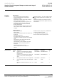
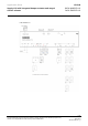
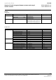
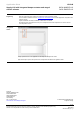
Application
configuration
Equipment
Channel/Signal
Settings example
On-board output
Supply air VAV position (integrated
actuator)
Y1, Y2; 3-position (integrated actuator)
Y1, Y2; 3-position
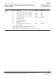
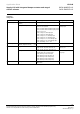
Heating coil valve position
Water; Y3, Y4; 3-position
Water; Y5, Y6; 3-position
Water; Y3; Pulse width modulation spring return
Water; Y5; Pulse width modulation spring return
Water; Y10; 0...10 V
Electric 1-stage; Y3; Normally open
Electric 1-stage; Y5; Normally open
Electric 2-stage; Y3, Y4; Normally open
Electric 2-stage; Y5, Y6; Normally open
Electric 3-stage; Y3, Y4, Y5; Normally open
Electric 3-stage; Y4, Y5, Y6; Normally open
Electric modulating; Y10; 0...10 V
Electric 2-stage; Y5, Y6;
Normally open
On-board input
Supply air VAV differential air
pressure (integrated sensor) (YS)
P1
P1
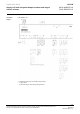
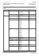
HVAC
Supply air VAV
Supply air VAV 12, press, duct area, ctr.
Supply air VAV 13, press, flow conv, ctr.
Supply air VAV 15, press, dependent ctrl.
Supply air VAV 13, press,
flow conv, ctr.
Heating coil
Hot water heating coil 11
Hot water heat.coil 12, sply.temp.ctrl.
Electric heating coil 11, mod.output
Electric heating coil 12, sply.temp.ctrl
Electric heating coil 13, 1 binary outp.
Electric heating coil 14, 2 binary outp.
Electric heating coil 15, 3 binary outp.
Electric heating coil 14, 2
binary outp.
Accessories
Room operator unit device
QMA1.N30H
QMX1.M34H
QMX1.M34H