
Operating Instructions and Installation Instructions


11
en
Congratulations on purchasing this Siemens appliance. You
have acquired a top-quality product, which will give you a lot
of enjoyment.
Please read this installation and operating instruction
manual carefully, then act accordingly! Store for future
reference.
Installation instructions
Install the small water heater as described in the
illustrated section. Observe the instructions in the text.
The illustrations can be found in the centre of the instruction
manual.
Unpacking
■ Inspect the new appliance for transport damage!
■ Please dispose of the packaging, and if applicable, the old
appliance in an environmentally-friendly manner.
I.
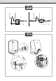
Scope of delivery
1 Housing
2 Temperature selector switch
3 Cold water supply
4 Hot water outlet
5 Mounting (2 screws, 2 wall plugs)
6 Documentation
7 Hand shower
8 Mixer tap
Open circuit operation (unpressurised) to supply just a
single tap:
Installation only with a suitable overflow fitting
– BZ 11114: Mixing tap with visible cross-connected body for
mounting on vertical surface and hand-held shower head
– BZ 11113: Mixing tap with visible cross-connected body
for mounting on vertical with pivoting outlet
Closed circuit operation (pressure-resistant), for several taps:
Installation only with permitted pressurised fittings and
safety valve
– AK 030300: Safety valve combination up to 5 bar
water pressure
– AK 040300: Safety valve combination up to 5 bar
water pressure with pressure reducing valve
Installation
II.
Dimensions
III.
Wall mounting
■ Note: When exchanging an appliance, check whether you
can re-use existing boreholes.
■ Mark the locations for the holes; drill the holes and insert
the wall plugs.
(DO15652: unpressurised operation with fitting BZ 11114
or DG15602: Pressure-resistant operation with safety
valve combination AK 030300/AK 040300)
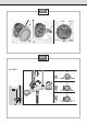
IV.
Water connection DO15652
■ Note: Make sure you mount the appliance vertically and
the wall is flat.
■ Connect the mixer tap.
■ Insert the connecting pipes to the mixer tap.
■ Mount the hot water heater on the wall.
■ Screw the connecting pipes to the heater and the
mixer tap.
Prevent the screw necks on the water heater from turning
by using a screw wrench.
V.
Water connection DG15602
Fig. 1: Unpressurised operation,
Fig. 2: Pressure-resistant operation
K Cold water
W Warm water
1 Prototype-tested diaphragm safety valve
2 Manometer test nozzle
3 Check valve
4 Test device for check valve
5 Pressure reducing valve
6 Stop valve
7 Tap fittings
Closed circuit operation (pressure-resistant)
■ Install in the vicinity of the tap at which most water is
taken.
■ Rinse the water pipes thoroughly to remove impurities
and contaminants before connecting the taps.
■ A safety valve (1) is to be fitted with a water pressure up to
0.5 MPa (5 bar). A pressure reducing valve (5) must be fit-
ted and set accordingly if the pressure exceeds this value.
■ A stop valve may not be fitted between the safety valve
(1) and the cold water supply.
The safety valve (1) outlet must always be open.
Safety valve combination AK 030300 and safety valve combi-
nation with pressure reducing valve AK 040300 can be fitted
with commercially available thermostat premixers.
Note: According to the energy conservation regulations, the
temperature in pipes may not exceed 60 °C if the length of
the warm water pipes exceeds 5 m.
■ Fill the appliance with water first until the water flows
from the fitting.