Desigo Total Room Automation User Guide Version 2.
Copyright Notice Copyright Notice Notice Document information is subject to change without notice by Siemens Switzerland Ltd. Companies, names, and various data used in examples are fictitious unless otherwise noted. No part of this document may be reproduced or transmitted in any form or by any means, electronic or mechanical, for any purpose, without the express written permission of Siemens Switzerland Ltd.
Table of Contents About This Document ....................................................................................................... 5 Document Revision History ................................................................................................. 9 1 Total Room Automation ................................................................................... 10 1.1 Central Functions ............................................................................................... 11 1.
5.2 5.1.5 Controlling Ventilation ......................................................................... 52 5.1.6 Raising Blinds ..................................................................................... 53 Standard Operation ............................................................................................ 53 5.2.1 Switching on Lighting .......................................................................... 53 5.2.2 Controlling Blinds .....................................
About This Document Document Revision History About This Document Purpose This guide describes the Desigo Total Room Integration (TRA), including specific operation procedures for the TRA application. Scope This document applies to the system version 2.1. Target Audience End-Users are the primary users of the system. Depending on the specific application, end users can be a building services engineer, a security guard, a member of the fire brigade, the facility manager, and so on.
About This Document Document Revision History Liability Disclaimer We have checked the contents of this manual for agreement with the hardware and software described. Since deviations cannot be precluded entirely, we cannot guarantee full agreement. However, the data in this manual are reviewed regularly and any necessary corrections included in subsequent editions. Suggestions for improvement are welcome.
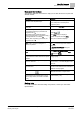
About This Document Document Revision History Document Conventions The following table lists conventions to help you use this document in a quick and efficient manner. Convention Examples Numbered Lists (1, 2, 3…) indicate a procedure with sequential steps. 1. Turn OFF power to the field panel. 2. Turn ON power to the field panel. 3. Open the panel. One-step procedures are indicated by a bullet point.
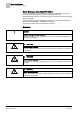
About This Document Document Revision History Safety Messages According ANSI Z535.6 The following examples show the ANSI standard safety messages used in this document to draw the reader’s attention to important information. ANSI distinguishes between personal injury safety messages and property damage warning messages. The personal injury safety messages have safety alert symbols and the following alert level labels: DANGER!, WARNING!, CAUTION! The label for property damage messages is: NOTICE.
About This Document Document Revision History Document Revision History Document Identification The document ID is structured as follows: ID_Language(COUNTRY)_ModificationIndex_ProductVersionIndex Example: A6Vnnnnnnnn_en_a_02 Document Revision History.
1 Total Room Automation Central Functions 1 Total Room Automation Desigo TRA offers solutions with lots of functionality and flexibility and permits energy-optimized plant operation without sacrificing comfort. PXC3 (freely programmable) and DXR2 (preconfigured applications) room automation stations are perfectly suited to exclusively automate heating, ventilation, and air conditioning plants in a room.
Total Room Automation Central Functions 1.1 1 Central Functions Central functions permit and support the centralized control and coordination of defined groups.
1 Total Room Automation Terms Used 1.2 Terms Used Term Description Lighting One or more luminaires in a room controlled by the local room operator unit or Management System. Emergency lighting One or more luminaires in a room that are turned on during an emergency by the fire department or central function (BACnet priority 2). Local room operator units are overridden until the emergency has ended. Shading General protection against the sun to reduce solar radiation into the building.
Room operation up to V5.1 Terms Used 2 2 Room Operation up to V5.
2 Room operation up to V5.1 Selecting Room 2.1 Selecting Room Views of the Rooms View in System Browser Floor plan view System Manager is in Operating mode. 1. In the System Browser or Floor plan view, select the room to operate. The room graphic opens and displays the most important values in the Operation tab. NOTE: Do not make changes in the dialog boxes. 2. 2.
Room operation up to V5.1 Editing Setpoints 2 Displays the room Operating mode properties. 3. Select the Value property and click Manual. 4. In the Value drop-down list box, select the Operating mode. 5. Click Send. The message Manual successful is displayed. In the Extended Operation tab the Present Priority and Priority Matrix changes to 8 or 13. NOTE: Successful operation only possible if you can write at a higher priority [➙ 77] than is displayed on the status bar for the Priority Matrix.
2 Room operation up to V5.1 Switching On and Off Lighting 4. In the Value drop-down list, enter a new value. 5. Click Send. The message Command successful is displayed. Under Advanced Operation change the Priority Matrix to 13. NOTE: Successful operation only possible if you can write at a higher priority [➙ 77] than is displayed on the status bar for the Priority Matrix. You can, for example, overwrite present priority 13 with priority 8. 2.
Room operation up to V5.1 Enabling Manual Operation 2.5 2 Enabling Manual Operation The room is selected and room graphic is displayed. 1. Select one or more settings to enable manual operation: – Values > Operating Mode Room – Settings > Setpoint Cooling Comfort – Settings > Setpoint Heating Comfort – Settings > Setpoint Shift A red frame is displayed when selected and the most important room values are listed in the Contextual pane of the Operation tab. 2. Select the Operation tab. 3.
2 Room operation up to V5.1 Positioning Blinds 2.7 Positioning Blinds The room is selected and room graphic is displayed. 1. Select the Blinds object and Value object . A red frame is displayed when selected and the most important values for this blinds object are listed in the Contextual pane of Operation tab. 2. Select the Operation tab. The blinds properties display. Position Height 1. Select the Height property and click Manual. 2.
Room operation as of V6 Positioning Blinds 3 3 Room Operation as of V6 Each room is displayed in a graphic with its unique features. The graphic supports two types of rooms: Room with one segment Room with Multiple Segments Room with One or More Segments The main information on a room is displayed in the Primary pane together with a list of segments. Select a segment to display detailed information in a Secondary pane.
3 Room operation as of V6 Room Detail 3.1 Room Detail Room Detail Display and Operation in Room Description 1 Displays the present room Operating mode. 2 Displays heating and cooling state. 3 Displays the present calculated heating and cooling setpoints. 4 Setpoint setting for heating and cooling. 5 Selected object is emphasized by a red frame. 6 Displays the detailed state of a room without segment information. 7 Displays the alarm and object state of a room without segment information.
Room operation as of V6 Segment List 3.2 3 Segment List Segment List Display on the Segment List Description 1 Selected segment is emphasized by a red frame. A corresponding link to the segment is displayed in the Related Items tab. 2 Displays the detail state of the segment (event enrollment of the room). 3 Displays the number of pending alarms in the segment. 4 Displays the number of pending errors in the segment. 5 Displays the number of objects that are out-of-order in the segment.
3 Room operation as of V6 Objects in Room 3.3 Objects in Room Objects in Room Available Objects in Room Description 1 Presence sensor 2 Outside temperature 3 Relative outside air humidity 4 The Green Leaf symbol indicates the room's efficiency state.
Room operation as of V6 Segment Detail 3.
3 Room operation as of V6 Selecting Room 9 Displays event enrollment for the segment 10 Displays the number of pending alarms in the segment 11 Displays the number of pending errors in the segment 12 Displays the number of objects that are out-of-order in the segment 13 Displays the number of objects that are overwritten in the segment 14 Displays the number of objects commanded at priority 8 in the segment 3.
Room operation as of V6 Selecting Room 3.5.1 3 Changing Operating Mode The room is selected and room graphic is displayed. 1. In the Contextual pane, click the Operation tab. 2. Select the Room Operating Mode property and click Manual. 3. In the Value drop-down list, select the Operating mode: – Comfort – Economy – Pre-Comfort – Protection The change to room Operating mode occurs at priority 13 and can be overwritten locally. 4. Click Send. The message Manual successful is displayed. 5.
3 Room operation as of V6 Selecting Room 3.5.1.1 Displaying Present Room Operating Mode The present room Operating mode is controlled based on various factors. The information displayed indicates the current Operating mode in the room. The room is selected and room graphic is displayed. 1. Click Next . Plant Operating modeand Temperature setpoint determination are displayed. The table displays the present object states (from left to right).
Room operation as of V6 Selecting Room 3 The Operation tab displays properties Room Operating mode and Comfort button. 2. Select the Comfort Button property and click Manual. 3. In the Value drop-down list select: – Active: The room is controlled for two hours to Comfort and then automatically set to Inactive. NOTE: The time can be set in the Setup and Service Assistant under the Time for Comfort Button property. – Inactive: The Comfort state is switched off and set to Enable after time expires. 4.
3 Room operation as of V6 Selecting Room 3.5.3.1 Creating or Editing a Scene The following items need clarification before creating, adding, or changing a scene: What does scene refer to? What objects are switched using the scene? In which sequence and at what delay times are the objects controlled? At what priority must objects be controlled (standard priority for scenes is 7)? The System Manager is in Engineering mode. A scene object is available in the application.
Room operation as of V6 Selecting Room 3.5.3.2 3 Assigning Objects to Scenes The scenes are created and have the correct designation. The Schedule tab is selected. 1. In System Browser, select Logical View. 2. Select Logical > [Hierarchy name] > [Hierarchy x ‒n] > [Room] > [Room segment] > Object type. 3. Drag the first object, for example, ROpModDtr (Room Operating mode) with drag-and-drop to the [Meeting] expander until the cursor changes.
3 Room operation as of V6 Selecting Room 8. Click Save . The new or edited configuration is saved on the TRA room automation station. 9. Test all scenes for functionality. Scenes are tested and operate as per the requirements of each scene. Object Assignment for Scenes Example: Scene Configuration ROpMod Prio. Light Prio. Blinds Prio. Fan Prio.
Room operation as of V6 Selecting Room 3 Text Group for Scenes NOTE 1: Texts added or changed on the Management System are not updated on the room operator unit. NOTE 2: The Maximum Value [➙ 31] must be modified on the scene object if the number of scenes is changed. The maximum value is determined by the number of scenes displayed in the Value drop-down list. 3.5.3.4 Modifying Maximum Value for Scenes The Scene object [➙ 27] is selected. 1. Click Object Configurator tab. 2.
3 Room operation as of V6 Selecting Room The Advanced Operation tab displays the properties. 2. Select the Priority Matrix Room Operating Mode property and click Manual. Displays the entry fields for Priority and Value. 3. In the Priority drop-down list, select option 08: Man.mode 2. NOTE: In principle, any priority between 1-15 can be selected. Other BACnet operator units also use priority 8 though. So that any BACnet operator unit can reset the override to priority 8. 4.
Room operation as of V6 Selecting Room 3.5.5 3 Editing Setpoints The room is selected and room graphic is displayed. 1. Select Room > Preset Setpoints and then: – Cooling – Heating A red frame is displayed when selected and the most important values for heating and cooling are displayed in the Contextual pane of the Operation tab. 2. Select for: – Cooling, property Cooling setpoint Comfort – Heating, property Heating setpoint Comfort 3. Click Manual. 4.
3 Room operation as of V6 Selecting Room The lines in green display the present setpoints for the room. 2. Back 3.5.6 switches you back to the room graphic. Switching Lighting On and Off Control is automatic by default based on installed switches, presence detector, and room request. Lighting can be switched on and off for individual segments as needed. The room is selected and room graphic is displayed. 1. Select Room > Segment(s) and then the desired room segment in the Names column. 2.
Room operation as of V6 Selecting Room 3.5.7 3 Positioning Blinds Control is automatic by default based on installed switches, presence detector, and room request. You can raise and lower blinds for individual segments as needed. The room is selected and room graphic is displayed. 1. Select Room > Segment(s) and then the desired room segment in the Names column. 2. Select the display in the column Blinds and click 0.00%.
4 Emergency Lighting Control Emergency Lighting Function 4 Emergency Lighting Control Emergency lighting installed in the building must be tested for availability on a regular basis. The frequency of the function test depends on: National standards Local standards Object use (hospital, office building, warehouse, cinema, etc.) Manufacturer information Eventually other factors The information can be compiled in a report after the function test and printed and saved for documentation purposes.
Emergency Lighting Control Test and Operating Functions 4.2 4 Test and Operating Functions The testing depth may vary depending on the frequency of a test. The table below lists all functions supported in Desigo CC. Emergency Lighting Functions Function Description Start function test The function test briefly places the device in a power outage state. This test does not impact battery capacity.
4 Emergency Lighting Control Evaluating Test Report 4.3 Evaluating Test Report A draft test report must be analyzed for possible faults in the emergency lighting. The measures for a fault depend on the availability of additional emergency lighting in this room. Test Report Evaluation of Test Report 4.4 4.4.1 Operating and Testing Emergency Lighting Emergency lighting is generally switched on and off in groups. Individual tests can be conducted manually for each emergency light.
Emergency Lighting Control Operating and Testing Emergency Lighting 4 7. Click Send. 4.4.2 Manually Testing Group The System Manager is in Operating mode. The online connection is available. 1. In the System Browser, select Application View. 2. Select Applications > Logics > Central Functions > [Hierachy name] > [Hierarchy 1-n] > [Central Functions for Emergency Lighting] > [Central Function Emergency Lighting for Zone A (CenEmgLgt ZoneA)]. 3. In the Contextual pane, click the Operation tab.
4 Emergency Lighting Control Operating and Testing Emergency Lighting 4.4.2.2 Starting Short Duration Test The short duration test places the device in power outage state long enough to calculate battery capacity without fully draining the battery. Central function Emergency Lighting and the corresponding group are selected. 1. Select the Emergency lighting control command. 2. In the Value drop-down, select option Start short duration test. 3. Click Change. The short duration test starts .
Emergency Lighting Control Operating and Testing Emergency Lighting 4.4.2.5 4 Overriding Rest Operating Mode Overrides the active power failed state and switches off emergency lighting. Can only be run for active power failure state. The function relieves batteries if the situation is safe. Central function Emergency Lighting and the corresponding group are selected. 1. Select the Emergency lighting control command. 2. In the Value drop-down list, select option Go to rest mode. 3. Click Change. 4.4.2.
4 Emergency Lighting Control Operating and Testing Emergency Lighting 4.4.2.9 Enabling Switch-off Pulse Switchable and dimmable devices that are not controlled by a local switch remain in an emergency state after a function or continuous test. The command sets the emergency state to Off. Central function Emergency Lighting and the corresponding group are selected. 1. Select the Emergency Lighting Control Command. 2. In the Value drop-down list box, select option Switch-off pulse. 3. Click Change. 4.4.
Emergency Lighting Control Operating and Testing Emergency Lighting 4.4.3 4.4.3.1 4 Creating Own Report The existing reports always acquire the entire building. Create your own reports for each zone that is tested. Create a report The Emergency Light reports are imported. 1. In the System Browser, select Application View. 2. Select Applications > Reports. 3. Open the Reports tab. 4.
4 Emergency Lighting Control Operating and Testing Emergency Lighting Defining Report Content 4.4.3.3 Defining Report Output The Emergency Light reports are opened. 1. Select the Settings tab. 2. For Report output click the symbol on the bottom right The Report Output Definition opens. . 3. Select Report Format (for example, PDF) and define the Destination type (for example, file). 4. Click Configure Folders. The Report Output Folders Configuration dialog box opens. 5.
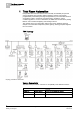
Emergency Lighting Control Operating and Testing Emergency Lighting 4.4.4 4 Automatically Testing Group When running tests, remember that there is no automatic feedback that the test is finished or the battery is fully charged. For this reason, plan for sufficient reserve time, to start the: Test report group 1 Test group 2 (charging time for batteries for group 1) Starting report group 2 Starting report group 1 Test group 1 13:00 15.03.20xx Test group 2 Charge time group 1 13:00 16.03.
4 Emergency Lighting Control Operating and Testing Emergency Lighting 8. Select Applications > Logics > Central Functions > [Hierarchy name] > [Hierarchy 1-n] > [Central Functions for Emergency Lighting] > [Central Function Emergency Lighting for Zone A (CenEmgLgt ZoneA)] > Emergency Luminaire (EmgLmnr) > Command Emergency Luminiare (EmgLmnrCtl). 9. Drag the Emergency Light Object to the Action expander. 10.
Operating Central Function Operating and Testing Emergency Lighting 5 5 Operating Central Function Entire sections of a building can be easily controlled using the central function [➙ 63], including: Fire Department Emergency Functions – Switching on Emergency Lighting [➙ 48] – Overriding Emergency Lighting Rest Operating Mode [➙ 51] – Controlling Ventilation [➙ 52] – Raising Blinds [➙ 53] Standard Operation – Switching On and Off Lighting [➙ 53] – Blinds up and down [➙ 54] – Changing Room Occupancy
5 Operating Central Function Fire Department Emergency Functions 5.1 8 Manual Manually switch on or off objects. 9 Auto Reset objects to automatic mode. Fire Department Emergency Functions Fire department emergency functions can also be used for maintenance and service work. No information is transmitted to the fire department when running these functions. Emergency lighting can be manually switched on for an entire building [➙ 48].
Operating Central Function Fire Department Emergency Functions 5.1.1.1 5 Switching Back to Automatic Mode Emergency lighting must be switched back to automatic mode after an emergency. 1. In the System Browser, select Application View. 2. Select Applications > Logics > Central Functions > [Hierarchy name] > [Hierarchy 1-n] > [Emergency Lighting (CenEmgLgt)]. 3. In the Contextual pane, click the Operation tab. Displays emergency lighting properties. 4. Select the Command value emergency property. 5.
5 Operating Central Function Fire Department Emergency Functions 5. Click Auto. 6. Click Send. The message Auto successful is displayed. 5.1.3 Switching on All Emergency Lighting for Multiple Zones Emergency lighting on in multiple zones using Text Viewer 1. In the System Browser, select Application View. 2. Select Applications > Logics > Central Functions > [Hierarchy name] > [Hierarchy 1-n] > [Central Functions for Emergency Lighting].
Operating Central Function Fire Department Emergency Functions 5.1.3.1 5 Switching Back to Automatic Mode Emergency lighting must be switched back to automatic mode after an emergency. 1. In the System Browser, select Application View. 2. Select Applications > Logics > Central Functions > [Hierarchy name] > [Hierarchy 1-n] > [Central Functions for Emergency Lighting]. The associated lighting objects are displayed in the Text Viewer. 3. Click the Type column. The list is sorted by type. 4.
5 Operating Central Function Fire Department Emergency Functions 5.1.5 Controlling Ventilation During an emergency, the fire department can control ventilation using the following operating modes: Automatic Emergency shutdown (lock) Purge (supply air, extract air fan on, dampers, and VAV dampers open Positive pressure Negative pressure 1. In the System Browser, select Application View. 2.
Operating Central Function Standard Operation 5.1.6 5 Raising Blinds The fire department can manually raise blinds during an emergency. 1. In the System Browser, select Application View. 2. Select Applications > Logics > Central Functions > [Hierarchy Name] > Blinds [Category] > [Emergency blinds control (CenEmgShd)]. 3. In the Contextual pane, click the Operation tab. Displays emergency blinds control properties. 4. Select Command Value. 5. Click Manual. 6.
5 Operating Central Function Standard Operation 6. Click Send. The message Command successful is displayed.
Operating Central Function Standard Operation 5.2.2 5 Controlling Blinds The System Manager is in Operating mode. The online connection is available. 1. In the System Browser, select Application View. 2. Select Applications > Logics > Central Functions > [Hierarchy Name] > Blinds [Category] > [Central Blinds Control (CenOpShd)]. The associated blinds objects are displayed in the Central Function Viewer. 3. Select the Operation tab. 4.
5 Operating Central Function Standard Operation 5.2.3 Changing Room Operating Mode The System Manager is in Operating mode. The online connection is available. 1. In the System Browser, select Application View. 2. Select Applications > Logics > Central Functions > [Hierarchy Name] > HVAC [Category] > [Central Operating Mode (CenOpMod)]. The associated operating modes are displayed in the Central Function Viewer. 3. Select the Operation tab. 4. Select the Comfort user (13) property and click Manual.
Operating TRA Room Automation Station Test TX-I/O Status V5.1 6 6 Operating TRA Room Automation Station Desigo CC does not fully support all features and functions on the TRA room automation station. Full support can, however, be achieved by operating the SSA Wizard [➙ 57] or ABT-SSA Wizard [➙ 57] for the TRA room automation station. Login on the TRA room automation station is simplified by defining the user groups and password in Desigo CC. 6.1 Test TX-I/O Status V5.
6 Operating TRA Room Automation Station Checking TX-I/O Status as of V6 6.2 Checking TX-I/O Status as of V6 The Setup and Service Assistant access BACnet objects on an automation station. For a description of Setup and Service Assistant, see document Desigo TRA Setup & Service Assistant (A6V10429119). NOTE: The user's guide Desigo TRA - Setup & Service Assistant is available for download on the Internet at: www.siemens.com/bt/A6V10429119.
Operating TRA Room Automation Station Checking TX-I/O Status as of V6 6.2.1 6 Opening the Room Automation Station The user name and password for logging onto the management system is defined in the Setup and Service Assistant. The user name and password must be entered each time if the user name is not defined. 1. In System Browser, select Logical View. 2. Select Logical > [Hierarchies] > [Room name]. 3. Select Related items tab and then Devices. 4. Click Display TRA Hardware Configuration.
6 Operating TRA Room Automation Station Checking TX-I/O Status as of V6 6.2.2 Opening a Room Segment The user name and password for logging on to the management system is defined in the Setup and Service Assistant. The user name and password must be entered each time if the user name is not defined. 1. In System Browser, select Logical View. 2. Select Logical > [Hierarchy name] > [Room name] > [Room segment]. 3. Select the Related items tab and then Device. 4. Click Display TRA Hardware Configuration.
Operating TRA Room Automation Station Checking TX-I/O Status as of V6 6.2.3 6 Opening an Event List The user name and password for logging onto the management system is defined in the Setup and Service Assistant. The user name and password must be entered each time if the user name is not defined. 1. In System Browser, select Logical View. 2. Select Logical > [Hierarchy name] > [Room name] > [HVAC] > Room segment state. 3. Select the Related Items tab and then Device. 4. Click Display TRA Event List.
6 Operating TRA Room Automation Station Checking TX-I/O Status as of V6 6.2.4 Acknowledging Alarm The user name and password for logging onto the management system is defined in the Setup and Service Assistant. The user name and password must be entered each time if the user name is not defined. 1. On the Alarm summary bar, click Alarm priority. A filtered alarm list opens. 2. Select the alarm and in the Source column, click Display text. 3. Select The Related items tab and then Device. 4.
Changing Central Function Checking TX-I/O Status as of V6 7 7 Changing Central Function There are central functions within TRA for occupancy, lighting, shading, and emergency lights. This permits joint control of rooms belonging to a group as well as manual operation on the management station or using a scheduler. The individual states can be displayed and switched [➙ 47] using the Central Function Viewer.
7 Changing Central Function HVAC 7.1 HVAC The figure illustrates (no data flow) how the central function acts on the individual rooms (for only two renters). Central Function HVAC Control Concept for Central Operator Function Function Description A Central Function Controls rooms for renter A. B Room operation Controls the room for renter A. C Central Function Controls rooms for renter B. D Room operation Controls the room for renter B.
Changing Central Function Lighting 7.2 7 Lighting The figure illustrates (no data flow) how the central function acts on the individual rooms (for only two renters). Central Function Lighting Control Concept for Central Operator Function Function Description A Fire alarm Switches on lighting in halls and stairwells. B Central Function Controls lighting throughout the building. C Central Function Controls lighting on an entire floor.
7 Changing Central Function Shading 7.3 Shading The figure illustrates (no data flow) how central functions act on the individual rooms (the west facade is not illustrated). Central Function Shading Control Concept for Central Operator Function Function Description A Fire alarm Raise blinds throughout the building. B Wind or frost. Raise blinds throughout the building. C Scheduler Acts on the entire building (priority 8 or 13). D Central Function Control blinds throughout the building.
Changing Central Function Emergency Lighting 7.4 7 Emergency Lighting The figure illustrates (no data flow) how the central function for emergency lighting acts on the individual emergency lights in a building. Central Function Emergency Lighting Control Concept for Central Emergency Lighting Function Description A Test group 1 Controls the test function for emergency lighting for group 1. B Test report group 1 Controls the test report for emergency lighting for group 1.
7 Changing Central Function Editing Central Functions NOTE: Group members can only be assigned within the same BACnet network and driver.
Changing Central Function Editing Central Functions SplyHw 7.5.1 Hot water supply chain 7 HVAC 3 Filter members The applicable list can be filtered (central functions and unassigned members). No wildcard permitted. Delete the text in this field to remove the filter. 4 Central function with assigned members Displays a list of available group masters. 5 Group master Selected group master with one group member. 6 Group member Selected group member.
7 Changing Central Function Editing Central Functions 7.5.2 Loading Data to the Central Function Editor The editor for central functions is enabled with your user group entitlement. The System Manager is in Engineering mode. Desigo TRA project data is imported. The online connection is available. 1. In the System Browser, select Application View. 2. Select Applications > Logics > Central Functions > [Hierarchy name] > [Hierarchy 1 ‒ Hierarchy n] > [Central function]. 3.
Changing Central Function Editing Central Functions 5. Click Save 7 . The defined configuration is saved on the Desigo TRA room automation station. NOTE: Use the filter function to limit the number of unassigned group members, for example, 114 for group members of room number 114. 7.5.4 Removing Group Member Assignments NOTICE Loss of Data during Download with ABT Pro: Edited group assignments are reset to the state of the last engineering data when downloading from ABT Pro.
8 Changing Room Segments Editing Central Functions 8 Changing Room Segments Room segment assignments can be changed using the Flexible Room Editor. The corresponding objects must be created or preconfigured to make a new assignment. NOTE: Group members can only be assigned within the same BACnet network and driver. Room Editor. Room Editor Description 1 Toolbar 2 Rooms and segments Displays a list of available rooms. 3 Selected room The arrow indicates that a segment is assigned to a room.
Changing Room Segments Toolbar 8.1 8 Toolbar The Room Editor toolbar has the following symbols: Room Editor Toolbar Symbol Name Description Save Saves the edited configuration in the system: Connection between room and segment Segment and room operator unit Room is set to used or unused System Browser is updated Load/refresh current view Loads the field data or updates the view of the Room Editor and its entries. The progress bar displays the status bar while loading data.
8 Changing Room Segments Reassigning Segment 8.2 Reassigning Segment A room segment can be reassigned for changes in use to a neighboring room segment. Reassign segment Local pushbutton Local pushbutton, with the same functionallity after reassignment Room with...
Changing Room Segments Reassigning Segment 8.2.1 8 Loading Rooms The Room Editor is enabled with your user group rights. The System Manager is in Engineering mode. The online connection is available. 1. In System Browser, select Logical View. 2. Select Logical > [Hierarchy name] > [Hierarchy 1 ‒ Hierarchy n] > [Room]. 3. Select the Flexible Room Editor tab. 4. Click Load/refresh current view. Data is uploaded from the TRA room automation stations and displayed in the Room Editor. 8.2.
8 Changing Room Segments Reassigning Segment 8.2.3 Refreshing System Browser for the Network The hierarchy displayed in the System Browser must be manually refreshed if Desigo CC or Engineering Tool changes segment assignments. Normally required after reimporting the data. The System Browser is automatically refreshed after saving using the Flexible Room Editor. The online connection is available. 1. In System Browser, select Management View. 2. Select Project > Subsystem networks > [Hierarchy name].
Appendix HVAC Room Control 9 9 Appendix 9.1 HVAC Room Control HVAC plants and their devices in the room influence the room conditions in closed rooms. A pleasant room climate is achieved during occupancy by controlling temperature, humidity, and air quality. HVAC plants in the room are divided up into plant families that differ in principle in design and how they act.
9 Appendix HVAC Room Control 9.1.1 BACnet Priorities for HVAC Applications The following table illustrates the priorities used in Desigo. Priorities in HVAC Priority Description Example 1 Emergency mode 1 ‒ 2 Emergency mode 2 Life safety (fan cannot be switched due to smoke) 3 Emergency mode 3 ‒ 4 Protection mode 1 ‒ 5 Protection mode 2 Locking via a dependent object (for example, the damper must be opened before the fan can be switched on).
Appendix Lighting Control 9.2 9 Lighting Control Control requires a variety of information about external influences and user actions to be able to cover requirements. The following illustration provides an overview of influences considered as part of lighting control.
9 Appendix Lighting Control Gray: Entire building Green/yellow: Rooms for a renter, for example, one floor. Orange: Local manual operation The control concept is oriented on the following principles: Distribute into independent functions that determine a lighting command. Prioritization of individual functions. Evaluation of all functions and decides, based on the priorities, which state the lighting assumes. 9.2.
Appendix 9 Lighting Control 9.2.1.1 Local Operation BACnet priority Room state An object is switched at priority 13 with the room operator unit. So that light switches, presence detectors, scheduler, or Management System (priority 13) are equal at switching. In other words, the last condition always applies. 8 13 13 8 13 13 7:00 17:00 18:00 Action 13 Off On Off 13 On Off On Off On Off On Off Local Operation for Lighting 9.2.1.
9 Appendix Lighting Control 9.2.1.3 Central Function The central function can override or switch multiple rooms in a building with the same priority. Central functions are classified by building requirements: Renter Sections Occupancy function (office/production) Floors Entire building Central functions use the same BACnet priorities as local control. So that override at priority 8 is permanent and only temporary at priority 13.
Appendix 9 Lighting Control 9.2.1.5 Remote Operation and Emergency 2 8 13 13 Action BACnet priority Room state All pending commands are overridden on emergency lighting until the state is reset.
Appendix Lighting Control 2 8 13 13 Action BACnet priority Room state 9 2 8 13 13 7:00 13 Off On On Off Off Emergency Lighting through Operation on the Management System 9.2.2 BACnet Priorities for Lighting The following table illustrates the priorities used in Desigo. Priorities in Lighting Priority Description Example 1 Emergency mode 1 ‒ 2 Emergency mode 2 Lighting can be switched on during a fire alarm to light escape routes or in support of first responders.
Appendix Shading Control 9.3 9 Shading Control Control requires a variety of information on environmental influences and user interventions to meet requirements. The following figure provides an overview of influences considered as part of blinds control. Positioning of blinds in the building, how the rooms are used, and assignment of rooms to organizational units determine what information acts on blinds control: Wind speed monitoring acts on all blinds in the building or portions thereof.
9 Appendix Shading Control 9.3.1 Operation Circumstances by Outside Influences Symbol Operating mode BACnetPriority Description Scheduler 13 Schedulers normally write at the lowest priority and can be overridden locally. Blinds switch 7 A blinds switch that cannot be overridden by the Management Station must be programmed at priority 7 (for example, screening room). 13 Blinds switches that can be overridden locally.
Appendix 9 BACnet priority Blinds state Shading Control 3 3 4 4 13 13 13 13 7:00 Action 13 Auto On Up Local 13 Down Up Normal Down Up Auto Up Auto Local Blinds Operation 9.3.1.1 Safety Functions A shading group can only be switched on and off if the present priority is higher than the present, pending priority. Switching is only possible if the priority is lower due to a safety function as soon as the normal state is reached.
9 Appendix Shading Control 9.3.2 BACnet Priorities for Shading The following table illustrates the priorities used in Desigo. BACnet Shading Priorities Priority Description Example 1 Emergency mode 1 ‒ 2 Emergency mode 2 Blinds can be raised during a fire alarm to permit evacuation through windows or access to emergency services personnel.
Appendix Shading Control 9 89 Siemens Building Technologies Desigo TRA User Guide A6V10415564_en_a_21 2015-06-23
Issued by Siemens Switzerland Ltd Building Technologies Division International Headquarters Gubelstrasse 22 CH-6301 Zug Tel. +41 41-724 24 24 www.siemens.com/buildingtechnologies Document ID A6V10415564_en_a_21 Edition 2015-06-23 © Siemens Switzerland Ltd, 2015 Technical specifications and availability subject to change without notice.