Desigo® Room Automation Compact room automation station, BACnet MS/TP, AC 24 V DXR2.M17C... For buildings with room pressurization and fume hood control applications, leveraging the functionality and flexibility of Desigo Room Automation applications.
Features Programmable The DXR2... automation stations provide the infrastructure for system and applicationspecific functions and can be programmed. Compact series The compact build permits mounting in narrow spaces and on standardized DIN rails, and is particularly well suited for compact panels or plants with integrated panel. Plug-in terminal blocks Plug-in terminal blocks to easily exchange room automation stations.
Functions The selected application and its parameters as well as input and output configuration determine the room automation station's functionality. A detailed description of functionality is available in the ABT (Automation Building Tool) online help. Communication ● MS/TP for system communication. ● Maximum of 30 MS/TP devices per network/trunk. ● FCOM – 3 wire daisy chain connection between room and fume hood controllers in a single pressurized space.
Technical design Voltage supply The supply provides controlled voltages for inputs and outputs. The room automation stations also supply AC 24 V and DC 24 V field supply. The supply is located in the device to simplify wiring and diagnostics. The processor controls voltage supply. This ensures clean conditions for the field devices connected to the I/Os during startup, shutdown, and undervoltage. Bus power supply The room automation station includes the bus power for KNX PL-Link.
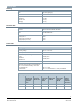
Type Stock number Designation QVE3001 S55720-S397 Airflow sensor 550-974P10 RS-485 Network Reference Terminator 550-975P100 120 Ohm ½ W Resistor Datapoint count 1 Product documentation Topic Title Document ID: Installation, cable length, topology Desigo TRA installation guide CM111043 Engineering and commissioning, workflow ABT online help n/a Commissioning Desigo TRA - Setup and Service Assistant CA111050 Product environmental declaration Product environmental declaration CM1E9205
Wiring Wiring must be sufficiently insulated to the available rated voltage. Sizing and fusing of the wiring depends on the connected load. Triac outputs AC 24 V Individual triac outputs may have a max. load of 12 VA, 24 V*0.5 A=12 VA. The following possibilities are permitted: ● Slow floating control actuators. ● Multiple motorized actuators with a total of max. 12 VA. ● 1 thermal actuator with 6 VA start load in a cold state. ● 2 thermal actuators with 12 VA start load each in a cold state.
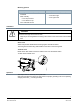
Mounting position Ambient temperature -5...45 °C (23...113°F) Ambient temperature -5...50 °C (23...122°F) 1. Overhead ● Wall, horizontal – From left to right 2. Wall, vertically – From right to left – From top to bottom – From bottom to top 3. On a horizontal surface Installation WARNING Risk of fire and injury due to short circuits! ● Adapt as per local regulations the wiring cross section to the rated value of the installed fuse.
Disposal The device is considered an electronic device for disposal in accordance with the European Guidelines and may not be disposed of as domestic garbage. ● Dispose of the device through channels provided for this purpose. ● Comply with all local and currently applicable laws and regulations. Warranty Technical data on specific applications are valid only together with Siemens products listed under Accessories, lab specific.
Technical data Housing Color RAL 7035 (light-gray) Dimensions See Dimensions Weight DXR2.M17C.. Terminal cover Packaging ca. 385 g ca. 80 g ca.
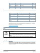
Inputs The inputs are protected against incorrect wiring AC 24 V. Inputs: Overview Type Inputs DXR2.X17C… 3 DI, 4 UI, 2 resistive inputs, SCOM Resistance sensor, analog (inputs X...) Type Range (over range) Resolution AI 1000 Ohm *) 1 kΩ (0...1.05 kΩ) 10 Ω Resistance sensor, analog (inputs B...) Type Range (over range) Resolution AI 10 kOhm *) 10 kΩ (0...10.5 kΩ) 50 Ω Temperature measurement, analog (inputs R1K...) Type Range (over range) Resolution AI PT1K 375 *) -40...70 °C (-45...
Current measurement, analog inputs (inputs X...) Type Range (over range) Resolution AI 120 4...20 mA (-1...11 V) 13 μA Load resistance 490 / 440 ohms, pulsing (cyclic interrogation of the I/O points) Note: if the peripheral device can not drive this load, the signal must be connected via a current measuring converter. Open connection can be detected. Supports 0…20 mA input range, with signal voltages >10 V. Use AI type U10 instead with an external resistor. Digital input (inputs X...
Power supply for field devices (outputs V~) Output voltage AC 24 V Permissible load DXR2.x17C... 750 mA / 18 VA overall Protection against overload Short-circuit proof Power supply for field devices (output V+) Output voltage DC 24 V Permissible load 100 mA / 2.
Wiring connections Pluggable screw terminals Copper wire or copper stranded wire with connector sleeves 1 x 0.6 mm ø to 2.5 mm2 (22 to 14 AWG) or 2 x 0.6 mm ø to 1 mm2 (22 to 18 AWG) Copper stranded wire without connector sleeves 1 x 0.6 mm ø to 2.5 mm2 (22 to 14 AWG) or 2 x 0.6 mm ø to 1.5 mm2 (22 to 16 AWG) Stripping length 6...7.5 mm (0.24...0.29 in) Slotted screws Size 1, tightening torque 0.6 Nm (0.
Standards, directives and approvals Product standard IEC/EN 60730-1 Automatic electronic controls for household and similar use Product family standard EN 50491-2, EN 50491-3, EN 50491-5 General requirements for Home and Building Electronic Systems (HBES) and Building Automation and Control Systems (BACS) EN 14175 part 6 Certified VAV system CET solution for laboratories and clean rooms at pressure range or 100…1000 Pa.
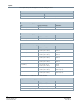
Pin Description Terminal 11, 12 KNX KNX connection +, - 21…23 MSTP Communication +, - Module Channel Isolated comm. ground reference 24…26 FCOM +, - Isolated comm. ground reference 31...41 inputs 10k Resistance input B1, B2 1 9…10 Universal input X1...X4 1 5…8 System neutral Field supply AC 24 V for active sensors ⏊ Field supply DC 24 V for active sensors V+ 1 1…3 Switching output AC 24 V ⏊ Y1...Y4 11 1…4 System neutral ⏊ 21 1…4 V~ USB USB interface 51...
Dimensions Issued by Siemens Industry, Inc. Smart Infrastructure 1000 Deerfield Pkwy Buffalo Grove IL 60089 +1 847-215-1000 Document ID A6V11868511 Edition 2021-06-16 © Siemens Industry, Inc., 2021 Technical specifications and availability subject to change without notice.