Desigo™ Web Interface User Guide A6V11938631_en--_a 2020-05-01 Smart Infrastructure
Edition notice Edition notice Technical specifications and availability subject to change without notice. This document may not be reproduced, disseminated to third parties or processed and its contents may not be used or disclosed without express permission. Non-compliance shall result in compensation for damages. All rights, including those resulting from a successful patent application and registration of a utility model or design patent, are reserved.
Copyright Copyright This document may be duplicated and distributed only with the express permission of Siemens, and may be passed only to authorized persons or companies with the required technical knowledge.
Trademarks Trademarks The trademarks used in this document are listed together with their legal owners in this section. The use of these trademarks is subject to international and national statutory provisions. Desigo® and Desigo® CC™ are registered trademarks of Siemens Schweiz AG. BACnet is a trademark of American National Standard (ANSI/ASHRAE 135-1995). Chrome and the Chrome logo are trademarks of Google LLC. Firefox is a registered trademark of Mozilla Foundation.
Table of Contents 1 About this document ............................................................................................................................... 8 1.1 Scope ............................................................................................................................................................ 8 1.2 Target reader .................................................................................................................................................
| 36 A6V11938631_en--_a
Cybersecurity disclaimer Cybersecurity disclaimer Siemens provides a portfolio of products, solutions, systems and services that includes security functions that support the secure operation of plants, systems, machines and networks. In the field of Building Technologies, this includes building automation and control, fire safety, security management as well as physical security systems.
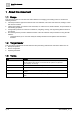
1 About this document Scope 1 About this document 1.1 Scope This manual provides an overview of the web interface for managing your building control. It contains the following sections: ● Overview provides a high-level overview of the user interface, main menu and status bar, settings, events and manual overrides. ● Object view provides an overview of the work area, an outline of icons, state indicators, and procedures for commanding properties.
Overview Accessing the PXC4/PXC5 web interface 2 2 Overview The web interface is a Web server component that is used to configure, commission, and maintain devices on the building network, including its connected field buses. The web interface is used for the following types of tasks: ● Setup, such as setting IP and BACnet addresses or setting the device language. ● Advanced operation and monitoring features, such as schedules and event logs. ● Generic operation of data points and properties. 2.
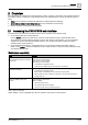
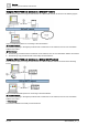
2 Overview Accessing the PXC4/PXC5 web interface Using the PXC4/PXC5 web interface on a BACnet/IP network The connection options for using the web interface on a BACnet/IP network are shown in the following Figure. Figure 1: BACnet/IP options for connecting to the web interface ① The web interface Connections ⓐ and ⓑ in the Figure provide access to all devices on the network, such as room automation stations and routers.
Overview Main menu and Status bar 2 2.2 Main menu and Status bar Figure 1: ① Main menu ● Object view Displays the work area, tree view, search bar, root icon and breadcrumb navigation. Object view [➙ 15] ● Configuration Submenus allow you to navigate, view, and engineer different device functions. Configuration [➙ 19] ● About Displays information regarding the About and Corporate Information. About [➙ 12] ● Account menu The Account menu is a button with the first letter of your username.
Overview 2 ② Main menu and Status bar Status bar Displays the current status of the device, events and alarms, overrides and the program state. ● Device state Displays the status of the device, (Operational, Loading required, or Not running). ● Events Click to display a list of events and objects in the state Alarm or Fault. Events [➙ 13] ● Manual overrides Click to display the number of objects that are physically overridden on the device.
Overview 2 Main menu and Status bar 2.2.2 Account menu The following table outlines the Account menu submenu. Submenu Setting Description View Settings of view ● ● ● Account Keep room user logged in The effect of this toggle depends on the role of who is currently logged-in. The setting of this toggle persists until the cache is cleared. See Managing automatic logout [➙ 26] Show unused objects Toggle ON to display unused objects during the current session.
2 Overview Main menu and Status bar Acknowledging current alarms 1. Click Events in the status bar and click for the desired alarm. 2. In the Event tab, click Acknowledge. The alarm is acknowledged and displays as . 2.2.4 Manual overrides Manual overrides displays objects that have been manually overridden. NOTE: Objects in the Manual overrides list may not be available for commanding if they have been overridden on the device.
Object view 3 Main menu and Status bar 3 Object view NOTICE Changes to the PXC4/PXC5 device configuration are saved in non-volatile memory every 5 minutes and whenever you log out of the device. ● Save and log out to immediately save changes to the device configuration. ● Changes to the device configuration are lost if a power cycle occurs within 5 minutes of the change and before you have logged out. When you log on, Object view displays by default.
Object view 3 Properties 3.1 Properties ● Click – – to display and modify the properties of an object. The Properties view displays in the right pane. If minimum and maximum values have been defined for any objects, this range displays above the value field. The Properties view allows you to command additional properties not available in the work area. ① Grey background Property is ready-only in the object’s current state. ② White background The property is ready for commanding.
Object view Special objects view 3 3.3 Special objects view Some special objects have a dedicated UI for viewing and editing.
3 Object view State indicators Indicator Description BACnet object type System function objects Diagnostics Diag Event log EvtLog Calendar Calendar Scheduler Schedule Primary Server 3.5 State indicators The State indicator icons represent the current condition of functions and/or objects associated with a room.
Configuration Device 4 4 Configuration The Configuration submenus allows you to navigate, view, and engineer different areas of your device. ● Device: Displays general information about the device. Device [➙ 19] ● Field bus: Summarizes the status of the automation station’s available field buses, provides an overview for direct field bus management and allows you to test data points and log the results.
4 Configuration Device ② Clear device – Stops the device, clears it, and clears the application configuration. The loaded application remains on the device and can be activated. The device must be configured. ③ Delete application – Stops the device, clears the application configuration, and keeps the existing device configuration. The device must be configured. The loaded application remains on the device and can be activated. The device must be configured.
Configuration 4 Field bus 4.2 Field bus The Field bus main page summarizes the status of the automation station’s available field buses. The following information displays for each field bus: ● Bus name ● Bus operating state ● Reliability state ● Number of configured devices / number of engineered devices that are connected.
Configuration 4 Reports 1. Click on a line item to display the data point test options. 2. Select the applicable test result from the drop-down list, (Failed or Passed). 3. Do one of the following: – – If the result is Failed, select a reason from the Comment drop-down list, and complete the Tested by and Assigned to fields. If the result is Passed, complete the Tested by field. 4. Click to save your changes and collapse the row, or click to cancel.
Configuration Reports 4 Data point test report The point test report contains detailed information on all data points in all existing field buses. Printing reports 1. Click Print. 2. Configure the printer settings and then, click Print. The reports are printed. Exporting reports 1. Click Save. 2. The reports are saved as an Excel file to your local drive. The Excel file is populated with the report data.
4 Configuration Assigned devices 4.4 Assigned devices This function is only available for PXC5 controllers and has a max of 50 assigned devices. Assigned devices displays information for the remote automation stations that are accessible for system control. Discovering and assigning devices Use this procedure to discover all devices communicating on the network and assign the desired devices for monitoring. 1. Navigate to Configuration > Assigned devices and click Discover to trigger a discovery.
Configuration 4 Users Adjusting the parameters for device discovery This procedure modifies the properties of device discovery. For example, you can limit the discovery to the local network and a specific range of device numbers. 1. Click Options to open the filtered properties of Discovered devices. 2. Use the following table to make selections for each parameter.
4 Configuration Users 4.5.1 Managing User profiles Use this procedure to set up additional user profiles. Navigate to Configuration > Users tab. Description Procedure Add a user 1. 2. Delete a user Change user password 3. 1. 2. 3. 1. 2. 3. 4. 5. Click Add user. Fill out the following fields: — User name — User role — Language — Date format — Time format — New password — Confirm password Click Add user to save the new user profile. Select the user profile you wish to delete. Click Delete user.
Scheduler 5 User interface 5 Scheduler Scheduler allows to you view and modify the weekly schedule and exceptions that override the schedule. This section discusses the following topics: ● Modifying a schedule ● Modifying the schedule default ● Copying one day’s activities ● Viewing and modifying Exceptions 5.1 User interface Default Scheduler view The Scheduler overview displays by default for the selected Scheduler object. Click Edit to display Edit mode.
5 Scheduler Modifying a schedule Work area views A switching point displays in the work area to indicate the time for a change of value (analog object) or setting (binary or multistate object). Analog object schedule ● Switching points display the value to which the referenced object(s) will be commanded. ● indicates a switching point that returns to the Schedule default.
Scheduler 5 Modifying the Schedule default Adding a switching point Use this procedure to add a new change of value or setting to the schedule. 1. While in Edit mode, click on the day and time where the switching point is needed. A new switching point displays. 2. Enter or select the value of the switching point. 3. Click Save to save the new switching point. NOTE: Cancel discards all changes since the last save.
5 Scheduler Copying one day's activities 2. Click the drop-down list to enter a new default value (analog object) or select a new default setting (binary or multistate object). 3. If the schedule should not attempt to control the referenced object(s) when a switching point is not in control or when a switching point’s value is set to Return to default, select the Return to default checkbox (analog object) or the Return to default setting (binary and multistate object). 4. Click OK to save your changes.
Scheduler Exception schedules 5 5.5 Exception schedules Exception schedules are used to manage deviations from the weekly schedule. ● When working online, exception dates can be added directly to the Scheduler object. Working with exceptions for the Scheduler object 1. While in Edit mode, click Exceptions to display a calendar view of exceptions for the current month. 2. To display a list of all exceptions for the schedule, click List view. ① Scheduler button Click to return to the weekly schedule.
5 Scheduler Exception schedules Adding an Exception 1. While in the Exceptions calendar, click Add in the upper right corner of the Calendar or List view. The Add exception dialog box displays. 2. From the Type drop-down, select Date, Date range, Weekday or Recurring and click OK. 3. Do one of the following: – – For Date or Date range, enter the desired date(s). For Weekday or Recurring, selected the desired values from the drop-down lists. 4. Select the Exception priority. 5.
Special workflows 6 Time synchronization 6 Special workflows 6.1 Time synchronization Time synchronization has three responsibilities: ● The device accepting the Time synchronization request. ● The device acting as a Time master. ● Time synchronization using Network Time Protocol (NTP). Prerequisite: Project has Time master enabled in ABT Site. NOTE: Once Time synchronization is started, it by default sends the UTC Time synchronization and Time synchronization to the recipients.
6 Special workflows Time synchronization The local time is updated, and this change displays in the Local time property of the device object. UTC Time synchronization UTC Time synchronization is used by a Time master to notify one or more remote devices of the correct Universal Time Coordinated (UTC) so that devices can synchronize their internal clocks with one another, and the intended date and time value is sent as part of the service request.
Special workflows Time synchronization A6V11938631_en--_a 6 35 | 36
Issued by Siemens Industry, Inc. Smart Infrastructure 1000 Deerfield Pkwy Buffalo Grove IL 60089 +1 847-215-1000 A6V11938631_en--_a © Siemens Industry, Inc., 2020 Technical specifications and availability subject to change without notice.