
Installation Instructions


Siemens Industry, Inc.
Smart Infrastructure
P/N 315-099458-104
OPEN/SHORT (Yellow) Normally OFF. When consistently illuminated, the HUB-
4 has detected an OPEN/SHORT in either the primary or
secondary wired communications line. When flashing,
there is a loss of communications between the HUB-4
main module, and the specific HUB-4 communication
port. If the HNET FAIL LED is also illuminated, this port
has been muted.
CARRIER FAIL (Yellow) Normally OFF. When consistently illuminated, the
HUB-4 has detected CARRIER FAIL with a modem
block or a polling supervision fail with a RS-485
Interface card between the HUB-4 and the remote
device. When flashing, there is a loss of communica-
tions between the modem or RS-485 Interface card
and the communications controller of the HUB-4 or
loss of communications between the HUB-4 and the
remote fire system.
Three rotary dial switches at the bottom of the front panel are used to set the HNET
network address of the HUB-4.
PRE-INSTALLATION Switch and Jumper Settings are required only on HUB-4, Main-2 and HUB-4, COM-2
boards that are not factory preassembled.
1. Network Address Switches: Set the three-digit HNET network address for
the HUB-4 using the three rotary dial switches located near the bottom of
the front panel. (Refer to Figure 1 for the location of the switches.) The
address for the HUB-4 must be the same as the address selected for it in
the NCC WAN. To set the address, turn the pointers on each of the three
dials to the numbers for the selected address. For example, if the address is
123, set the pointer for the HUNDREDS dial to “1”, set the pointer for the
TENS dial to “2”, and set the pointer for the ONES dial to “3”. The range of
allowable addresses is from 001 to 251 (leading zeros must be used).
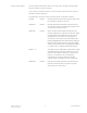
2. HUB-4, Main-2 Board (Switch S2): Currently Not Used. All switches must
be set to the ON position.
HNET
S2
ON
OFF
12345678
HUB-4 MAIN-2
(Bottom side of board)
Figure 2
Location of S2 On HUB-4 Main-2