
Installation Instructions


Siemens Industry, Inc.
Smart Infrastructure
P/N 315-099458-103
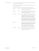
Controls and Indicators The front panel of the HUB-4 contains one reset switch, 15 LEDs and three HNET
address switches as shown in Figure 1.
A reset switch is located on the top of the front panel. Pushing the reset switch re-
initializes the HUB-4 operation.
The LEDs follow the reset switch and their functions are defined as follows:
POWER (Green) Normally ON. When illuminated, indicates that power
for the HUB-4 is applied to the card.
CARD FAIL (Yellow) Normally OFF. When illuminated, indicates that the
card microprocessor has failed. May illuminate for 2-4
seconds when initially powered.
HNET FAIL (Yellow) When consistantly illuminated, the HUB-4 has de-
tected an HNET loss of supervision of the NCC. When
the HUB-4 detects an HNET failure, it will cause all
configured ports to shut down communication to
remote units. The muted ports will be indicated by a
flashing OPEN/SHORT LED. When flashing rapidly, the
HUB-4 has been addressed via the front panel HNET
address select switches with an inappropriate address,
i.e., address zero, or addressed above 252 decimal.
PORTS 1 – 4 The LEDs for each independent modem block module
or RS-485 Interface module are referred to as ports.
When all three LEDs are flashing for a specific port,
that port is considered to be an unspecified,
unconfigured port that has detected a modem
originate signal or RS-485 data from a remote unit.
GND FAULT (Yellow) Normally OFF. When illuminated, indicates that the
HUB-4 has detected either a negative or positive
ground fault on its field wiring.