
Installation Instructions


Siemens Industry, Inc.
Smart Infrastructure
P/N 315-099458-1015
345678
10 11 12 13 14 15 16
18 19 20 21 22 23 24
ONE SLOT OF CC-5 #1 WITH HUB-4
INSTALLED
AA ABB BB
+
--++
--
AABB
++
--
TB1
TB2
LLM-1
12 34
12 34
AB
--
Mount the LLM
Refer to LLM
093530, for further information
80 ohm max per pair
1.0uf Max line
14-18AWG Twisted pair or twisted shielded pair
RPM
12345 6
DO
NOT
USE
RS-485 interface on the HUB
TB1
LLM-1
12 34
12 34
Optional Shield
Maximum voltage
120 OHM EOL
Power limited to NFPA
Positive or negative ground fault detected
ohms on CC
PORT 2
RS-485
* The LLM-1 inserts
10 ohms between
TB1 and TB2
terminals 2 and 3
(20 ohms total).
*
* The LLM-1 inserts
10 ohms between
TB1 and TB2
terminals 2 and 3
(20 ohms total).
*
++--
P/N 140-049099
MODEM OR
OR RS-485
INTERFACE
Port #2
MODEM OR
OR RS-485
INTERFACE
Port #3
x
MODEM OR
OR RS-485
INTERFACE
Port #4
x
RXD TXD
x
1.
2.
3.
4.
5.
6.
7.
8.
NOTES:
Chassis
Ground
Chassis
Ground
12
9
17
A
+
PSC-12
TB4+
-
AB
++
-1 in the enclosure with the RPM.
-1 installation instructions, P/N 315-
(Does not include LLM-1)
-to-line capacitance
-4 must be set to Style 4
8Vp-p
72
p
er NEC 760
<5K
-5 1-16
x
The interface type
(Modem or RS-485)
must match on each
COM-2 card. If only
one interface is used
on a COM-2 card, it
must be placed on
Port #1 or Port #3
NCC-WAN
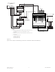
Figure 16
Style 4 Wiring Between HUB-4’s (with RS-485 interface) to RPM (NCC WAN only)
12341234567 8
910111213141516
17 18 19 20 21 22 23 24
ONE SLOT OF CC-5 #1 WITH HUB-4
INSTALLED
AAAABB BB
++
--++
--
AABB
++
--
TB1
TB2
LLM-1
12 34
12 34
AABB
++
--
MODEM OR
OR RS-485
INTERFACE
Port #3
MODEM OR
OR RS-485
INTERFACE
Port #4
MODEM OR
OR RS-485
INTERFACE
Port #2
120 OHM EOL
120 OHM EOL
MOM
1.
80
3.
Power limited to NFPA
4.
Maximum current
5.
Maximum voltage
P/N 140-049099
* The LLM-1 inserts
10 ohms between
TB1 and TB2
terminals 2 and 3
(20 ohms total).
*
2.
14
P/N 140-049099
6.
Mount the LLM
-
+
x
x
x
Chassis
Ground
7.
Positive or negative ground fault detected
on CC
PSC-12
TB4+
-
-4
NIM-1W Installed Inside
MXL enclosure
ohms max per pair (Does not include LLM-1)
72 per NEC 760
150mA
8Vp-p
-18AWG Twisted pair or twisted shielded pair
-1 inside the MXL enclosure
TB3 or TB4
x
The interface type
(Modem or RS-485)
must match on each
COM-2 card. If only
one interface is used
on a COM-2 card, it
must be placed on
Port #1 or Port #3
<5K ohms
-5 1-16
NCC-WAN
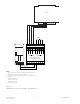
Figure 17
Style 4 Wiring to NIM-1W (with RS-485 interface) (NCC WAN only)