
Installation Instructions


Siemens Industry, Inc.
Smart Infrastructure
P/N 315-099458-1013
1
2
3
4
1
2
3
4
TB1TB2
LLM-1
1 2 3 4 5 6 7 8
9 10 11 12 13 14 15 16
+
+
--
+
+
--
+
+
--
+
+
--
A
AA
AB
BB
B
B
BB
B
A
AA
A
17 18 19 20 21 22 23 24
MODEM OR
RS-485 INTERFACE 3
ONE SLOT OF CC-2/5
WITH HUB-4 INSTALLED
121110987654321
121110987654321
WAIO
TB2
TB1
MODEM OR
RS-485 INTERFACE 4
TO PSC-12 TB4+
TO PSC-12 TB4-
MODEM OR
RS-485 INTERFACE 2
120 OHMS EOLR
120
OHMS
EOLR
TERMINATION
RESISTORS
-
+
-
+
2
+
1
-
INPUT
TERMINALS
ON NEXT
WAIO
TO ADDITIONAL
WAIOs (MAX 16)
TERMINATE LAST
WAIO WITH 120 OHM
RESISTOR ON
TERMINALS 3, 4
1
2
3
4
1
2
3
4
TB1TB2
LLM-1
1 2 3 4 5 6 7 8
9 10 11 12 13 14 15 16
+
+
--
+
+
--
+
+
--
+
+
--
A
AA
AB
BB
B
B
BB
B
A
AA
A
17 18 19 20 21 22 23 24
MODEM OR
RS-485 INTERFACE 3
ONE SLOT OF CC-2/5
WITH HUB-4 INSTALLED
121110987654321
121110987654321
WAIO
TB2
TB1
MODEM OR
RS-485 INTERFACE 4
TO PSC-12 TB4+
TO PSC-12 TB4-
MODEM OR
RS-485 INTERFACE 2
120
OHMS
EOLR
TERMINATION
RESISTORS
-
+
-
+
2
+
1
-
INPUT
TERMINALS
ON NEXT
WAIO
1
2
3
4
1
2
3
4
TB1TB2
LLM-1
-
+
-
+
5
-
6
+
TO ADDITIONAL
WAIOs (MAX 16)
TERMINATE LAST
WAIO WITH 120
OHM RESISTOR
ON TERMINALS
3, 4 AND 5, 6
120
OHMS
EOLR
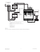
Figure 12
Typical Class B (Style 4) Wiring to WAIO Connection (NCC WAN only)
NOTES
1. Mount the LLM-1 within the monitored fire panel enclosure.
Refer to the LLM-1 Installation Instructions, P/N 315-093530, for
further information.
2. Positive or negative ground fault detected at <25K ohms on CC-
5 pins 1-16.
3. 200 ohms max per pair.
0.34 μF max line to line.
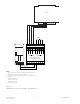
Figure 13
Typical Class A (Style 7) Wiring to WAIO Connection (NCC WAN only)
NOTES
1. Mount the LLM-1 within the monitored fire panel
enclosure. Refer to the LLM-1 Installation Instructions, P/N
315-093530, for further information.
2. Positive or negative ground fault detected at <25K ohms
on CC-5 pins 1-16.
3. 200 ohms max per pair.
0.34 μF max line to line.