
Installation Instructions


Siemens Industry, Inc.
Smart Infrastructure
P/N 315-099458-1010
NOTES
1. Mount the LLM-1 within the MXL enclosure.
Refer to the LLM-1 Installation Instructions, P/
N 315-093530, for further information.
2. Positive or negative ground fault detected at
<25K ohms on CC-5 pins 1-16.
3. 14-18 AWG 8 miles max.
20 AWG 5 miles max.
22 AWG 3 miles max.
0.6 μF max line to line.
560 OHM EOL
P/N 140-988066
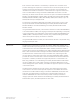
Figure 9
Typical Class B (Style 4) HUB-4 Wiring Connection to CMI-300 on MXL (NCC WAN only)
ELECTRICAL RATINGS Input Power
24V Back Plane Current 0
Screw Terminal 24V Current 400mA
6.2V Back Plane Current 30mA
24V Standby Current 400mA
Output Power
Each modem 2V peak-to-peak max
Channel pair 1.3mA max
Maximum line attenuation -23dbm @ 2.5KHz
Each RS-485 Interface 8V peak-to-peak
RS-485 output pair 75mA during message transmission