
Engineering Documentation
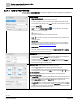
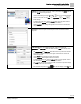
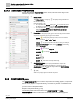
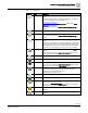
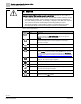
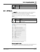
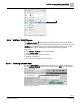
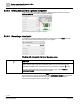
Table Of Contents
- Copyright Notice
- 1 About this document
- 2 Desigo Control Point Operation engineering topics
- 2.1 Tool-free configuration of a Desigo Control Point device
- 2.1.1 Connecting to the Desigo Control Point device
- 2.1.2 Performing the initial login
- 2.1.3 Configuring the Network port for IP (PXG3.Wx00 and PXM… touch panel)
- 2.1.4 Activating the application (PXG3.Wx00 and PXM… touch panel)
- 2.1.5 Assigning devices to the Desigo Control Point device
- 2.1.6 Updating the Network port for a browser connection (PXM… touch panel)
- 2.1.7 Subscribing to the time master and time synchronization for Assigned devices
- 2.1.8 Configuring for kiosk graphics on a touch panel
- 2.2 Tool-free commissioning of the Operation application
- 2.3 Data point integration overview
- 2.4 Plant view Tools
- 2.4.1 Using the graphics wizard to create a graphic
- 2.4.2 Editing a graphic
- 2.4.3 Removing a graphic
- 2.4.4 Displaying the URL of a graphic
- 2.4.5 Exporting graphics for sharing across jobs
- 2.4.6 Importing graphics
- 2.4.7 Enabling graphics and kiosks for room users to view
- 2.4.8 Defining graphics as a startup page
- 2.5 Working with kiosk graphics
- 2.6 Using engineering notations
- 2.1 Tool-free configuration of a Desigo Control Point device
- 3 Graphics engineering with Graphics Builder
- 3.1 Graphics Builder overview
- 3.2 Using the Builder pane tools
- 3.3 Graphics libraries
- 3.4 Workflows
- 3.5 Working with dashboards
- 3.5.1 The Facility manager dashboard user interface
- 3.5.2 The Public dashboard user interface
- 3.5.3 Adding and editing a text box
- 3.5.4 Adding or replacing a background image
- 3.5.5 Adding information from a trended data point
- 3.5.6 Adding external media to a dashboard
- 3.5.7 Working with gauges
- 3.5.8 Editing charts
- 3.6 Creating end-user room graphics
- 3.7 Advanced functionality
- 4 Tips and tricks
- 4.1 Updates required after a time zone change
- 4.2 APPLY BATCH TAGS > Custom Filter button is reserved for future use
- 4.3 Graphic components within models cannot be modified
- 4.4 A graphic with relative binding that includes data points from different branches of the hierarchy cannot be created at the Root level
- 4.5 Relative hyperlinks cannot be added to a graphic at the Root level
- 4.6 Relative hyperlinks in a graphic are broken if the graphic is engineered offline and then imported to another device
- 4.7 Haystack interface
- 4.8 Automatic logout from the Operation application causes Graphics Builder to temporarily stop working
- Index

Graphics engineering with Graphics Builder
Using the Builder pane tools
62 | 138
Siemens
A6V11211560_enUS_b
Building Technologies
2019-01-15
3.2.1.1 BASIC PROPERTIES
Use the BASIC PROPERTIES to modify the graphic name or change the appearance
of the selected component.
General properties
● Name field (not labeled)
The name of the currently-selected graphic component.
To rename a graphic, click on an open area of the graphic background until the
current graphic name displays in the Name field. Enter a new name for the graphic
and click SAVE .
Note: Do not use SAVE AS GRAPHIC to rename a graphic. This creates a
second copy of the current graphic.
(Unlock / Lock)
Locks the current properties for the selected component.
Lock a component to prevent it from being selected and moved while you are
editing the graphic.
● Classes field
Specifies classes from a pre-defined cascading style sheet (css) to change the
appearance of a component. For more information, see the J2 Graphics Builder
documentation (https://finproducts.atlassian.net/wiki).
SAVE MODEL
Saves the currently-selected component to the COMPONENTS > MODELS
pane so that the component can be reused.
BACKGROUND
Select a color or image to use as a background.
● To select a color, click the COLOR field to open the palette. Select a background
color and click the COLOR field again to save your selection.
● To select an image, select IMAGE from the TYPE drop-down list. Click Browse to
select a file from the models, images and other components that have been
imported to the Desigo Control Point device.
POSITION & SIZE
Adjust the position, width and height of the selected component.
● Adjust the X and Y settings to change the position of a component.
● To resize a graphic, click on an open area of the graphic background until the
current graphic name displays in the Name field. Then adjust the W and H settings.
Poll Interval (Ms) field
The interval for polling the database and updating values in the entire graphic.
Scale To Fit toggle switch
● If Scale To Fit is ON, the graphic is automatically resized to fit the display when the
graphic is rendered. To use a single graphic on devices with different size screens,
switch Scale To Fit ON. By default, Scale To Fit is ON for graphics in the
Supersample graphics library.
● If Scale To Fit is OFF, the graphic always displays at the size specified in the W
and H fields. For end-user room graphics, switch Scale To Fit OFF to maximize the
available space for controls and to maintain the end-user room widget sizes when
the graphic is viewed on different size screens.