
Advance DataNET Hub User's Manual

32 •
••
• Installation 2000585-001
DataNET Copper Connections, Continued
Step Action
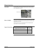
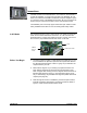
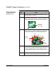
1. Plug the DataNET Hub Signal Equalizer Board into the se-
lected Port interface connector.
2. Connect the board’s pig tail leads to the corresponding hub
downlink port channel; red lead to (+) terminal, black lead to
(-) terminal and white lead to Gnd terminal. See Figure 2-1.
Master Port
Connectors
TB15 – TB18
3. Connect the downlink signal wires to the removable port
connector (TB1) on top of the equalizer board. Positive to
(+) terminal; and Negative to (-) terminal. See Figure 2-1.
.
SW2
SW1
SW3
TB1Port
Connector
Board
Connector
GND
-
+
4. If conduit is used the cable shield is only terminated at one
end of the cable. If shield is terminated at this end connect it
to terminal 3 (GND) on board. If using cable gland connec-
tors, cable gland will always connect the shield to the chas-
sis.
5. Set the switches on the board to the correct settings; see
DataNET Hub Signal Equalizer Board Settings page 34.
Down Link Wiring with
DataNET Hub Signal
Equalizer Board