
Operating instructions


Commissioning (software)
2.8 Encoder Commissioning
Control Units CU240S
2-56 Operating Instructions (Compact), 04/2006, A5E00766042B AA
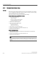
Table 2-19 Encoder voltage settings
On
OFF
34
9(QFRGHU
VXSSO\
9(QFRGHU
VXSSO\
34
9(QFRGHU
VXSSO\
9(QFRGHU
VXSSO\
34
9(QFRGHU
VXSSO\
9(QFRGHU
VXSSO\
34
9(QFRGHU
VXSSO\
9(QFRGHU
VXSSO\
Encoder supply
voltage
0 V 24 V 5 V 24 V
Encoder type No encoder HTL encoder TTL encoder HTL encoder
Warning
DIP switches 3 and 4 in ON position provide a supply voltage of 24 V to the encoder.
Therefore it is not allowed to connect a TTL encoder to the inverter if both DIP switches, 3
and 4 are in ON position.
2.8.2 Parameterizing the Encoder Interface
Encoder parameterization
To enable the Encoder to function correctly with the inverter, the parameters in the table
below, must be modified.
Table 2-20 Encoder parameters
Parameter Name Values
r0061 Rotor speed Indicates the speed of the rotor. Used to check that the system is
working correctly.
r0090 Rotor angle Indicates the current angle of the rotor. This function is not available on
single input channel encoders.
P0400[3] Encoder type
• 0: No encoder
• 2 or12: Quadrature encoder (channel A + B) –
the term "quadrature" means two periodic functions separated by a
quarter cycle or 90 degrees
Status word of
encoder
Displays status word of encoder in bit format:
0 No Bit 00 - Encoder module active
1 Yes
0 No Bit 01 - Encoder error
1 Yes
r0403
Bit 02 - Signal OK 0 No