
Operating instructions


Installing/Mounting
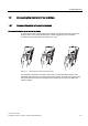
1.1 Fitting the CU to the PM
Control Units CU240S
Operating Instructions (Compact), 04/2006, A5E00766042B AA
1-11
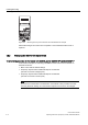
Table 1-2 Typical Encoder connections
Encoder pin
assignment
1xP8001 Encoder
designations
Enocder terminals Rotary Pulse Encoder
1XP8001-1/Up = 10 V … 30 V (HTL)
1XP8001-2/Up = 5 V ± 5 % (TTL)
A U
a2
BN
B U
p
+ 24 V or + 5 V
C U
a0
Z
D U
a0
ZN
E U
a1
A
F U
a1
AN
G U
as
-
H U
a2
B
K 0 V 0 V
L 0 V -
M U
p
-
B
D
E
F
H
K
A
L
M
C
G
J
6KLHOG
(QFRGHU
FRQQHFWRU
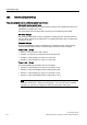
The encoder voltage is using the general I/O DIP switches 3 and 4.
The following table shows the possible settings:
Table 1-3 Encoder voltage settings
On
OFF
34
9(QFRGHU
VXSSO\
9(QFRGHU
VXSSO\
34
9(QFRGHU
VXSSO\
9(QFRGHU
VXSSO\
34
9(QFRGHU
VXSSO\
9(QFRGHU
VXSSO\
34
9(QFRGHU
VXSSO\
9(QFRGHU
VXSSO\
Encoder supply
voltage
0 V 24 V 5 V 24 V
Encoder type No encoder HTL encoder TTL encoder HTL encoder
Warning
DIP switches 3 and 4 in ON position provide a supply voltage of 24 V to the encoder.
Therefore it is not allowed to connect a TTL encoder to the inverter if both DIP switches, 3
and 4 are in ON position.