
Installation manual


Accessories
7.3 Braking Resistor
Power Module PM240
Hardware Installation Manual, 07/2009, A5E00807525B AD
109
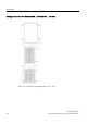
Table 7- 23 Dimension data: Braking resistor, all data in mm and (inches)
Order No. of the braking resistor 6SE6400-4BD11-0AA0 6SL3201-0BE12-0AA0
FSA FSB Suitable for Power Module (HO)
0.37 kW ... 1.5 kW 2.2 kW ... 4 kW
Order-No. of the suitable Power
Module
6SL3224-0BE13-7UA0
6SL3224-0BE15-5UA0
6SL3224-0BE17-5UA0
6SL3224-0BE21-1UA0
6SL3224-0BE21-5UA0
6SL3224-0BE22-2 . A0
6SL3224-0BE23-0 . A0
6SL3224-0BE24-0 . A0
L 230 (9.05) 239 (9.40)
L1 217 (8.54) 226 (8.89)
D 43.5 (1.71) 43.5 (1.71)
W 72 (2.83) 149 (5.86)
W1 56 (2.20) 138 (5.43)
The braking resistors can be installed horizontally or vertically. The connections on vertically
installed resistors must be at the bottom.
The braking resistors for the FSA and FSB frame sizes are designed as sub-chassis
components. If the PM240 Power Modules of the FSA or FSB frame size are operated
without line reactor, the braking resistors can also be installed under the Power Modules.
The braking resistor can be positioned outside the cabinet or switchgear room. This enables
the resulting heat loss around the Power Modules to be dissipated. This reduces the level of
air conditioning required.