
Operating instructions


Installing/Mounting
4.6 Installation Check List
Control Units CU240S
Operating Instructions, 10/2007, A5E00766042B AC
45
6,1$0,&6
*
352),1(7 866
352),1(7
3%3%
(6
67$57(5
352),1(7
&RQWUROOHU
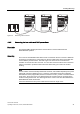
Figure 4-8 Topology 3: Routing
Note
Pay attention to the following restrictions:
• A ring-type topology is not permissible.
• SINAMICS does not support routing from PROFIBUS to PROFINET and vice versa.
See also
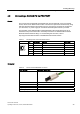
Assembly Instructions RJ45 Plug
(http://support.automation.siemens.com/WW/view/en/23175326/130000)
4.6 Installation Check List
Installation check list
Before power is applied to the inverter/motor system, the following checks should be
performed:
Check that: ✓
1 The environmental conditions conform to the inverter/motor specifications
2 The inverter and the motor are securely mounted
3 The inverter and motor are correctly installed with adequate cooling provision
4 The motor and the application/equipment are ready to start, i.e. safe state - motor can rotate
5 The inverter is correctly earthed/grounded
6 The input power (supply) voltage matches the inverter's nominal input voltage
7 The input power (mains) fuses are the correct type and installed correctly
8 The motor connections are connected to ensure the correct direction of rotation of the motor at start-up
9 The motor and mains connections are connected and tightened to the required specification
10 The motor connections are not reversed - the motor will start but serious damage may occur to the connected
equipment
11 The motor cable is routed away from other cables
12 The control connections are connected and tightened to the required specification
13 No tools or other objects that can cause damage to the system are present
14 The inverter is the only power source to the motor