
Operating instructions


Installing/Mounting
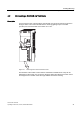
4.4 Connecting a CU240S DP or CU240S DP-F via PROFIBUS DP
Control Units CU240S
Operating Instructions, 10/2007, A5E00766042B AC
39
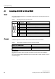
Table 4-5 Permissible cable length for one segment
Baud rate Max. cable lengths for one segment
9.6 kbaud … 187.5 kbaud 1000 m (3280 ft)*
500 kbaud 400 m (1312 ft)*
1.5 Mbaud 200 m (656 ft)*
3 Mbaud … 12 Mbaud 100 m (328 ft)*
∗ Repeaters can be installed to increase the length of a segment.
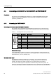
Cable installation rules
During installation the bus cable must not be:
● twisted
● stretched or
● compressed.
Supplementary constraints as regards electromagnetic compatibility must also be observed.
Connectors
To connect the PROFIBUS cable to the PROFIBUS DP interface, a bus connector of one of
the types described in the following table is recommended.
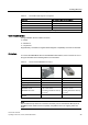
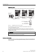
Table 4-6 Recommended PROFIBUS connectors
Order Number 6GK1 500-0FC00 6GK1 500-0EA02
PG socket No No
Max. baud rate 12 Mbaud 12 Mbaud
Terminating resistor On/Off switch On/Off switch
Outgoing cable unit 180° 180°
Interfaces
PROFIBUS nodes
PROFIBUS bus cable
9-pin sub D socket
4 modular terminals for wires up
to 1.5 mm
2
9-pin sub D socket
4 modular terminals for wires up
to 1.5 mm
2
Connectable PROFIBUS cable
diameter
8 ± 0.5 mm 8 ± 0.5 mm
Note
We recommend only these two connectors since they can be used without difficulty for all
SINAMICS G120 models and are completely compatible in terms of outgoing cable unit
angle.