
Operating instructions


Installing/Mounting
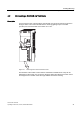
4.3 Connecting a CU240S via USS on RS485
Control Units CU240S
36 Operating Instructions, 10/2007, A5E00766042B AC
4.3 Connecting a CU240S via USS on RS485
Socket
The Control Units CU240S have a 9-pin female sub-D socket for connecting the inverter via
an RS485 interface.
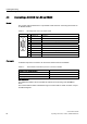
Table 4-1 PIN assignment of the 9-pin sub-D socket
Pin Designation Description
1 - Unused
2 - Unused
3 RS485P Receive- and transmit signal (+)
4 - Unused
5 0 V Ground reference
6 - Unused
7 - Unused
8 RS485N Receive- and transmit signal (-)
9 - Unused
X Screen (casing) Potential equilisation
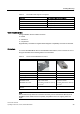
Connector
A standard 9 pin sub-D connector can be used for USS connection via RS485.
Table 4-2 Technical data of standard 9-pin sub-D connector for RS485
Standard 9 pin sub D connector
PG socket No
Max. baud rate 115200 baud
Outgoing cable unit 180°
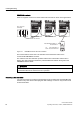
Bus termination
The RS485 termination can be activated via switches on the housing of the SINAMICS
G120.
The bus termination switch is illustrated in figure "Control Units CU 240S" in section "Layout
and Block Diagram".