
Operating instructions


Description
3.3 Layout and Block diagram
Control Units CU240S
Operating Instructions, 10/2007, A5E00766042B AC
19
3.3 Layout and Block diagram
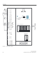
Layout characteristics of the CU240S
The figure below shows the various interfaces of the different types of Control Units.
&86
&86'3
&86'3)
&8631
&8631)
Figure 3-1 Control Units CU240S
① MMC slot ⑧ Terminals for fail-safe functions
② General I/O DIP switches ⑨ RS485 interface via SUB-D connector
③ PROFIBUS DP address DIP
switches
⑩ PROFIBUS DP interface via SUB-D
connector
④ Option port
⑤ Inverter status LED
⑪ PROFIBUS DP (PROFIsafe) interface
via SUB-D connector
⑥ Inverter status LEDs and fail-safe LEDs ⑫ PROFINET interface RJ45
⑦ Bus terminator switch ⑬ Power Module interface