
Operating instructions


Communication
6.4 Communication via PROFIBUS
Control Units CU240S
Operating Instructions, 10/2007, A5E00766042B AC
151
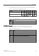
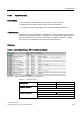
The PROFIBUS DP address can be set between 1 and 125, as shown in the table below.
Table 6-26 Example address for the PROFIBUS DP interface
DIP switch 1 2 3 4 5 6 7
Add to address 1 2 4 8 16 32 64
Example 1: Address = 3 = 1 + 2
Example 2: Address = 88 = 8 + 16 + 64
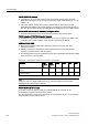
The valid address range is shown in the table below:
Table 6-27 PROFIBUS DP address
DIP switch
settings
Meaning
0 PROFIBUS DP address is determined by P0918
1 … 125 Valid PROFIBUS DP address
126, 127 Invalid PROFIBUS DP address
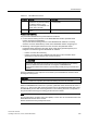
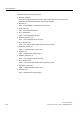
PROFIBUS DP parameters
The following parameters must be set to start-up the PROFIBUS DP interface:
Table 6-28 PROFIBUS DP parameters
Parameter Content
P0918 PROFIBUS address
P0700 Selection of command source
P0922 Selection of PROFIBUS standard telegram
P1000 Selection of frequency setpoint
P2038 Selection of communication profile
P2042 Selection of the ident number (native or NAMUR) send to PLC
r2050 Process data setpoint source (BICO)
P2051 Process data actual values (BICO)
P2041 Communication board functions
P2040 Process data telegram failure time
P0927 Modification source for parameters
r2054 Communication board diagnostics