
Operating instructions


Communication
6.2 Cyclic Communication
Control Units CU240S
Operating Instructions, 10/2007, A5E00766042B AC
139
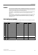
An example
In the remote control operating mode the commands and target values come from a superior
control system to the inverter by means of a PROFIBUS. By switching to local operation, the
command and target value source is switched and operation is now performed locally on the
system by means of digital inputs and the analog target values.
Local operation = Command data set 0: In this case the command code of the terminal strip
P0700 Index 0 = 2 and the frequency target value is the analog target value P1000
Index 0 = 2.
Remote operation = Command data set 1: In this case the command code corresponds with
the control word (word 0) received from the PROFIBUS P0700 Index 1 = 6 and the
frequency target value corresponds with the control word 1 received from the PROFIBUS
P1000 Index 1 = 6.
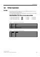
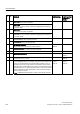
Default assignment control word 2 (STW2)
The control word 2 is assigned as a default as follows. This can be changed by using BICO.
Table 6-18 Assignment control word 2 (for VIK/NAMUR not defined)
Bit Value Meaning P0922 = 1 P0922 = 350 P0922 = 352
0 1 Fixed frequency selection Bit 0 P1020 depends on P070x = P1020 P1020 depends on P070x
1 1 Fixed frequency selection Bit 1 P1021 depends on P070x = P1021 P1021 depends on P070x
2 1 Fixed frequency selection Bit 2 P1022 depends on P070x = P1022 P1022 depends on P070x
3 1 Fixed frequency selection Bit 3 P1023 depends on P070x = P1023 P1023 depends on P070x
4 – Not used -- -- --
5 – Not used -- -- --
6 – Not used -- -- --
7 – Not used -- -- --
8 1 Enable Technology Controller 0.0 = P2200 0.0
9 1 Enable DC Brake 0.0 = P1230 0.0
10 – Not used -- -- --
11 1 Enable Droop Speed Controller Enable Droop Enable Droop Enable Droop
1 Torque Control 12
0 Speed Control
0.0 = P1501 0.0
13 0 External Fault 1 1.0 = P2106 1.0
14 – Not used -- -- --
15 – Not used -- -- --