
Operating instructions


Communication
6.2 Cyclic Communication
Control Units CU240S
Operating Instructions, 10/2007, A5E00766042B AC
133
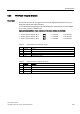
6.2.3 PROFIsafe Telegram Structure
Description
The fail-safe functions can be triggered via the fail-safe digital inputs FDI0 and FDI1 or via
PROFIsafe signals (see P9603 and 9803).
To use PROFIsafe for triggering the fail-safe functions the G120 GSD file must be installed
in the control system e.g. SIMATIC S7.
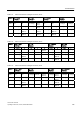
Input and output address, 6 byte each (input and otuput address are identical)
• Byte 0 (process data 0), Bit 0:
STO 0 = selected 1 not selected
• Byte 0 (process data 0), Bit 1:
SS1 0 = selected 1 not selected
• Byte 1 (process data 1), Bit 0:
SLS 0 = selected 1 not selected
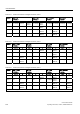
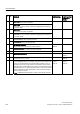
Table 6-8 Intput addresses for PROFIsafe signals
Address Function
1 E 0.0 STO bit from inverter
2 E 0.1 SS1 bit from inverter
…
9 E 1.0 SLS bit from inverter
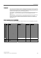
Table 6-9 Output addresses for PROFIsafe signals
Address Function
1 A 0.0 STO bit to inverter
2 A 0.1 SS1 bit to inverter
…
9 A 1.0 SLS to from inverter