
Operating instructions


Functions
5.4 Setpoint sources
CU240S and CU240E Control Units, FW 3.2
Operating Instructions, 03/2009, A5E02440075B AA
97
5.4.2 Using analog inputs as a setpoint source
Frequency setpoint via analog input [for P1000 = 2]
Analog setpoints are read-in via the corresponding analog inputs. The setting specifying
whether the analog input is a voltage input (10 V) or current input (20 mA) must be made via
P0756 and in addition using the DIP switches on the Control Unit housing.
Note
Only analog input 0 (AI0) can be used as a
bipolar
voltage input.
Depending on the AI type of the source, a suitable connection must be established.
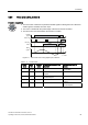
Table 5- 17 Set and parameterize the analog input for use as setpoint source
Terminal No.
and
Significance
Parameters Description
Setting the DIP
switch
OFF: Voltage input (factory setting)
ON: Current input
9VXSSO\
9VXSSO\
7HUPLQDWH
7UDFN$
7HUPLQDWH
7UDFN%
7HUPLQDWH
7UDFN1
21
234
5
67
$,
$,
2))
3 AI0+
4 AI0-
P0756 [0] Analog input 1
10 AI1+
11 AI1-
P0756 [1] Analog input 2
P0756 = 0 Analog input type (AI)
Defines the analog input type and enables analog input
monitoring.
0: Unipolar voltage input (0 … +10 V) (factory setting)
1: Unipolar voltage input with monitoring (0 … +10 V)
2: Unipolar current input (0 mA …20 mA)
3: Unipolar current input with monitoring (0 … 20 mA)
4: Bipolar voltage input (-10 … +10 V)
P0757 = 0 Value x1 for AI scaling [V or mA]
P0758 = 0.0 Value y1 of AI-scaling
This parameter shows the amount of x1 as a % of P2000
(reference frequency)
P0759 = 10 Value x2 for AI scaling [V or mA]
P0760 = 100 Value y2 of AI-scaling
This parameter shows the amount of x2 as a % of P2000
(reference frequency)
P0761 = 0 Width of the AI dead zone