
Operating instructions


Functions
5.3 Command sources
CU240S and CU240E Control Units, FW 3.2
94 Operating Instructions, 03/2009, A5E02440075B AA
5.3.2 Assigning functions to digital inputs
Assigning control commands to digital inputs as command sources [P0701…P0709]
The digital inputs are pre-assigned with certain control commands in the factory. However,
these digital inputs can be freely assigned to a control command. Depending on the Control
Unit version, SINAMICS inverters are equipped with up to 9 digital inputs.
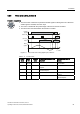
Table 5- 14 Factory setting of the digital inputs
Terminal no.: Digital input no. Control command Available in CU...
Terminal 5: Digital input 0 (DI0) Switch motor on/off (ON/OFF1)
Terminal 6: Digital input 1 (DI1) Reverse direction of rotation
Terminal 7: Digital input 2 (DI2) Fault acknowledgment
Terminal 8: Digital input 3 (DI3) Selects fixed frequency 1
Terminal 16: Digital input 4 (DI4) Selects fixed frequency 2
Terminal 17: Digital input 5 (DI5) Selects fixed frequency 3
CU240E
CU240S
CU240S DP
CU240S PN
CU240S DP-F
CU240S PN-F
Terminal 40: Digital input 6 (DI6) Selects fixed frequency 4
Terminal 41: Digital input 7 (DI7) Locked
Terminal 42: Digital input 8 (DI8) Locked
CU240S
CU240S DP
CU240S PN
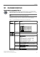
Table 5- 15 Changing the digital input settings
Terminal no.: Digital input no. Parameter Description
P0003 = 2 Extended access to the parameters
Terminal 5: Digital input 0 (DI0)
P0701 = …
Terminal 6: Digital input 1 (DI1)
P0702 = …
Terminal 7: Digital input 2 (DI2)
P0703 = …
Terminal 8: Digital input 3 (DI3)
P0704 = …
Terminal 16: Digital input 4 (DI4)
P0705 = …
Terminal 17: Digital input 5 (DI5)
P0706 = …
Terminal 40: Digital input 6 (DI6)
P0707 = …
Terminal 41: Digital input 7 (DI7)
P0708 = …
Terminal 42: Digital input 8 (DI8) P0709 = …
Possible values for P0701 to P0709:
0: Digital input locked
1: Switch motor on/off (ON/OFF1)
2: Activate motor CW
3: Motor coasts to standstill (OFF2)
4: Rapid stop with ramp (OFF3)
9: Fault acknowledgement
10: Jog mode CW
11: Jog mode CCW
12: Change direction of rotation (reverse)
13: Increase frequency of motorized potentiometer
14: Increase frequency of motorized potentiometer
15: Select fixed frequencies (bit 0)
16: Select fixed frequencies (bit 1)
17: Select fixed frequencies (bit 2)
18: Select fixed frequencies (bit 3)
25: Enable signal for DC brake
27: Enable signal for PID technology controller
29: External fault
33: Disable additional frequency setpoint
99: The digital input can be freely used for the BICO technology
If you enable one of the digital inputs to be freely used for BICO technology (P701…P709 =
99), then you must interconnect this digital input to the required control command.
If value 99 is assigned to the digital input to define its function, this can only be reversed by
restoring the factory setting.