
Operating instructions


Functions
5.2 Inverter control
CU240S and CU240E Control Units, FW 3.2
90 Operating Instructions, 03/2009, A5E02440075B AA
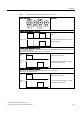
5.2.5 Three-wire control, method 1
Function description
● The first control command is a permanent enable signal for starting the motor. When this
enable signal is canceled, the motor stops.
● CW rotation is activated with the positive edge of the second control command.
● CCW rotation is activated with the positive edge of the third control command.
R
R
R
(QDEOH
VLJQDO
0RWRU21
&:
0RWRU21
&&:
0RWRU
VSHHG
&RPPDQGLJQRUHG
$FWLYH
$FWLYH$FWLYH
2))
W
Figure 5-5 Three-wire control using digital inputs, method 1
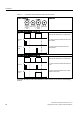
Table 5- 9 Function table
Enable
signal
Motor ON /
CW
Motor ON /
CCW
Function
0 Not
relevant
Not
relevant
OFF1: The motor decelerates to a standstill
1 0→1 0 The motor accelerates to the setpoint
1 0 0→1 The motor accelerates to the inverted setpoint
1 0 0 No effect on the direction of rotation.
1 1 1 OFF1: The motor decelerates to a standstill
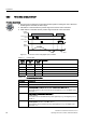
Table 5- 10 Parameterizing the function
Parameter Description
P0700 = 2 Controls the motor using the digital inputs of the inverter
P0727 = 2 Three-wire control, method 1
P0701 = 1 The enable signal to power-up the motor is issued with digital input 0
Further options:
The enable signal can be issued with any other digital input, e.g. with digital input 3
via P0704 = 1
P0702 = 2 CW rotation is activated with digital input 1
Further options:
CW rotation can be activated with any other digital input, e.g. with digital input 3 via
P0704 = 2
P0703 = 12 CCW rotation is activated with digital input 2
Further options:
CCW rotation can be activated with any other digital input, e.g. with digital input 3
via P0704 = 12