
Operating instructions


CU240S and CU240E Control Units, FW 3.2
Operating Instructions, 03/2009, A5E02440075B AA
27
Connection
3
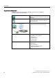
3.1 Procedure for installing the frequency inverter
Prerequisites for installing the inverter
Check that the following prerequisites are fulfilled before you install the inverter:
● Are the components, tools and small parts required for installation available?
● Are the ambient conditions permissible? See: Technical data (Page 227)
● Have the cables and wires been routed in accordance with the applicable regulations?
See: EMC-compliant connection (Page 39)
● Are the minimum distances from other equipment complied with? (Cooling sufficient?)
See: Chapter: Dimensions, hole drilling templates, minimum clearances, tightening
torques (Page 31)
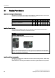
Installation sequence
1. Install the Power Module (detailed instructions are provided in the Installation Manual for
the Power Modules
(http://support.automation.siemens.com/WW/view/en/30563173/133300
))
– Remove the terminal covers - where applicable
– Connect motor cable and power cable
– Terminate the shield over a large area, if necessary using a shield connection set
– Refit the terminal covers
2. Mount the Control Unit
– Open the terminal covers of the Control Unit
– Connect the control lines to the terminals
– Terminate the shield over a large area, if necessary using a shield connection set
– Close the terminal covers again
3. Control Unit – for operation in a higher-level control – connect to the fieldbus
– For PROFIBUS DP and CANopen connect it via the 9-pin sub D connector
– For RS 485, connect it via the two-part bus connector
4. To commission the drive unit, either plug-in the operator control/display instrument
(operator panel) or connect the inverter to the PC using the PC connection kit.
Installation has now been completed and you can begin commissioning.