
Operating instructions


CU240S and CU240E Control Units, FW 3.2
Operating Instructions, 03/2009, A5E02440075B AA
219
Messages and fault codes
7
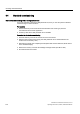
Overview
The G120 inverter features the following diagnostic indicators:
● LEDs on the Control Unit
For a detailed overview of LED statuses, see "LED status indicators" (below).
● Fault and alarm numbers
– Alarms provide warning information. They do not trigger any response from the
system and do not need to be acknowledged.
– If a fault occurs, the inverter shuts down and the "SF" LED on the Control Unit lights
up. The inverter cannot be switched on again until the fault has been rectified. Once
the fault has been rectified, it must be acknowledged.
Alarm and fault numbers are displayed on the operator panel, STARTER, or a higher-
level control system.
Note
A description of all of the alarms and faults as well as the associated counter-measures
are provided in the STARTER online help or in the List Manual in Section "Faults and
alarm messages".