
Operating instructions


Functions
5.12 Safety functions
CU240S and CU240E Control Units, FW 3.2
202 Operating Instructions, 03/2009, A5E02440075B AA
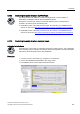
4. Select the "Enables" tab. None of the fail-safe inputs are activated in the factory setting,
i.e. no input is assigned to a safety function
5. Click on the button
on the lower edge of the STARTER screen and enter the safety password. The default
password is '12345'.
The inverter outputs alarm A1698 to signal that safety settings are currently being
changed. Further, the following LEDs flash on the Control Unit: RDY, ES, STO, SS1, and
SLS.
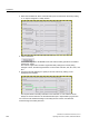
6. Assign the fail-safe digital input 0 (FDI0) to the STO function by clicking on the
appropriate two switches.
The required function is always selected on two channels, i.e. both switches should
always be closed to activate. An activated fail-safe input is represented by a green line.
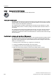
You can then make additional settings in the safety function screens or finalize the
commissioning of the safety functions.