
Operating instructions


Functions
5.12 Safety functions
CU240S and CU240E Control Units, FW 3.2
198 Operating Instructions, 03/2009, A5E02440075B AA
5.12.2 Connecting-up the fail-safe inputs
Connecting sensors to fail-safe inputs
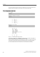
The fail-safe inputs of the inverter are designed for connecting electromechanical sensors
with two NC contacts.
It is not possible to directly connect sensors with two NO contacts and antivalent contacts (1
NO contact and 1 NC contact).
Figure 5-42 Sensors that can be connected to the fail-safe inputs
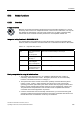
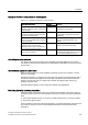
The following diagrams show the principle connection options for fail-safe inputs for the case
that all of the components are mounted and installed inside a control cabinet.
● Connecting sensors with electromechanical contacts, e.g. Emergency Stop mushroom
pushbuttons and end position switches
● Connecting electronic sensors, e.g. SIMATIC FS-400 light curtains
● Connecting safety relays, e.g. SIRIUS 3TK28.
● Connecting fail-safe outputs, e.g. SIMATIC F digital output modules
6LQDPLFV*
89
)',$
)',%
Figure 5-43 Connecting an electromechanical sensor
6,0$7,&)6
5*
6HQGHU
6,0$7,&)6
5*
5HFHLYHU
6,1$0,&6*
89
)',$
9'&
0
)',%
99
8V
266'
266'
8V
Figure 5-44 Connecting-up an electronic sensor inside a control cabinet