
Operating instructions


Functions
5.11 Operation in fieldbus systems
CU240S and CU240E Control Units, FW 3.2
190 Operating Instructions, 03/2009, A5E02440075B AA
Information about the S7 program
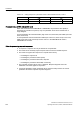
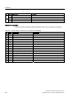
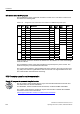
The hexadecimal numeric value 047E is written to control word 1. The bits in control word 1
are listed in the following table.
Table 5- 88 Assignment of the control bits in the inverter to the SIMATIC flags and inputs
HEX BIN Bit in
STW1
Significance Bit in
MW1
Bit in
MB1
Bit in
MB2
Inputs
0 0 ON/OFF1 8 0 E0.0
1 1 ON/OFF2 9 1
1 2 ON/OFF3 10 2
E
1 3 Operation enable 11 3
1 4 Ramp-function generator enable 12 4
1 5 Start ramp-function generator 13 5
1 6 Setpoint enable 14 6
7
0 7 Acknowledge fault 15
7 E0.6
0 8 Jog 1 0 0
0 9 Jog 2 1 1
1 10 PLC control 2 2
4
0 11 Setpoint inversion 3 3
0 12 Irrelevant 4 4
0 13 Motorized potentiometer ↑ 5 5
0 14 Motorized potentiometer ↓ 6 6
0
0 15 Data set changeover 7 7
In this example, inputs E0.0 and E0.6 are linked to the -bit ON/OFF1 or to the "acknowledge
fault" bit of STW 1.
The hexadecimal numeric value 2500 specifies the setpoint frequency of the inverter. The
maximum frequency is the hexadecimal value 4000.
The process data is written to logical address 256 of the inverter in the cyclic time slice of S7
(e.g. OB1) and read from logical address 256 of the inverter. The logical addresses for field
bus communication were defined in HW Config.
STEP 7 sample program for acyclic communication
Simple S7 program for parameterizing the inverter
The S7 program, which supplies data for acyclic communication between the inverter and
the central control is valid for PROFIBUS.
For PROFINET, instead of blocks SFC58 and SFC59, use blocks SFB52 and SFB53.
The number of simultaneous requests for acyclic communication is limited. More detailed
information can be found in the Internet
(http://support.automation.siemens.com/WW/view/en/15364459
):
352),%86
352),%86