
Operating instructions


Functions
5.11 Operation in fieldbus systems
CU240S and CU240E Control Units, FW 3.2
Operating Instructions, 03/2009, A5E02440075B AA
183
Control and status words
Description
The control and status words fulfill the specifications of PROFIdrive profile version 4.1 for
"speed control" mode.
Control word 1 (STW1)
Control word 1 (bits 0 to 10 in accordance with PROFIdrive profile and VIK/NAMUR, bits 11
to 15 for SINAMICS G120 only).
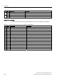
Table 5- 84 Assignment of control word 1
Bit Value Significance Comments
0 OFF1 Shutdown, deceleration on the RFG ramp, pulse inhibit
when f < f
min
.
0
1 ON Switches the inverter to "ready for operation" mode. The
direction of rotation must be specified via bit 11.
0 Coast to standstill (OFF2) Immediate pulse inhibit, drive coasts to standstill. 1
1 No coasting to standstill All "coast to standstill" (OFF2) commands are canceled.
0 Quick stop (OFF3) Quick stop: Shut down with the deceleration ramp that can
be additionally set.
2
1 No quick stop All "quick stop" (OFF3) commands are canceled.
0 Disable operation Control and inverter pulses are locked. 3
1 Enable operation Control and inverter pulses are enabled.
0 Reset ramp-function generator (RFG) RFG output is set to 0 (quickest possible deceleration),
inverter remains ON.
4
1 Enable ramp-function generator (RFG)
0 Inhibit ramp-function generator (RFG) The setpoint currently provided by the ramp-function
generator is "frozen".
5
1 Enable ramp-function generator (RFG)
0 Deactivate setpoint The value selected at the ramp-function generator input is
set to 0 (zero).
6
1 Enable setpoint The value selected at the ramp-function generator input is
enabled.
7 1 Fault acknowledgment Fault is acknowledged with a positive edge; the inverter
then switches to "starting inhibit" mode.
0 JOG 1 OFF Drive brakes along the ramp. 8
1 JOG 1 ON The drive ramps-up to the setpoint for the jog mode
(direction of rotation: CW = clockwise).
0 JOG 2 OFF Drive brakes along the ramp. 9
1 JOG 2 ON The drive ramps-up to the setpoint for the jog mode
(direction of rotation: CCW = counter-clockwise).
0 No PLC control Process data invalid, "sign of life" expected. 10
1 PLC control Control via interface; process data valid
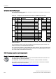
352),%86
352),%86
352),1(7
352),1(7