
Operating instructions


Functions
5.11 Operation in fieldbus systems
CU240S and CU240E Control Units, FW 3.2
Operating Instructions, 03/2009, A5E02440075B AA
181
Parameter index (IND), second word
3.(
,1'
3:(
VW
ZRUG
QG
ZRUG
UG
DQG
WK
ZRUG
3DJHLQGH[6XELQGH[,1'
3DUDPHWHUFKDQQHO
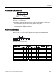
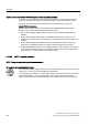
Figure 5-35 IND structure (cyclic)
● The field sub-index is an 8 bit value which, in cyclic data transfer mode, is transferred in
the more-significant byte (bits 8 to 15) of the parameter index (IND).
● In this case, the least-significant byte (bits 0 to 7) in the parameter index selects the
parameter page for additional parameters.
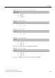
Rules for the parameter range
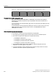
The bit for selecting the parameter page functions as follows:
When it is set to 1, an offset of 2000 is applied in the inverter to the parameter number
(PNU) transferred in the parameter channel request before the data is transferred.
,1'
DGFEI H
Figure 5-36 IND page index (cyclic)
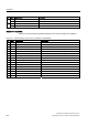
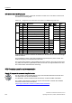
Table 5- 82 Regulations for setting the PNU
Page index Bit
Parameter range
a d c b f e 9 8
Hex value + PNU
0000 … 1999 0 0 0 0 0 0 0 0 0x00 0 – 7CF
2000 … 3999 1 0 0 0 0 0 0 0 0x80 0 – 7CF
4000 … 5999 0 0 0 1 0 0 0 0 0x10 0 – 7CF
6000 … 7999 1 0 0 1 0 0 0 0 0x90 0 – 7CF
8000 … 9999 0 0 1 0 0 0 0 0 0x20 0 – 7CF
… … … … … … … … … … …
32.000 … 33.999 0 0 0 0 0 1 0 0 0x04 0 – 7CF
… … … … … … … … … … …
64.000 … 65.999 0 0 0 0 1 0 0 0 0x08 0 – 7CF