
Operating instructions


Functions
5.11 Operation in fieldbus systems
CU240S and CU240E Control Units, FW 3.2
Operating Instructions, 03/2009, A5E02440075B AA
171
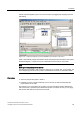
Add the required telegram type to slot 1 of the inverter by dragging and dropping it from the
HW catalog.
Figure 5-30 Define the telegram type of the SINAMICS G120 inverter in the control
STEP 7 automatically assigns the address range containing the process data for the inverter.
Standard telegram 1 occupies four bytes of input data and four bytes of output data.
Note
Defining the telegram type in the inverter
The telegram type setting in HW Config only applies to the controller side. In the inverter, the
same telegram type must be set by means of STARTER or the BOP via parameter P0922.
Final steps
● Save and compile the project in STEP 7.
● Establish an online connection between your PC and the S7 CPU and download the
project data to the S7 CPU.
The inverter is now connected to the S7 CPU. The communications interface between the
CPU and inverter is specified by the PROFIdrive profile. An example of how you can supply
this interface with data can be found in this manual.