
Operating instructions


Functions
5.11 Operation in fieldbus systems
CU240S and CU240E Control Units, FW 3.2
152 Operating Instructions, 03/2009, A5E02440075B AA
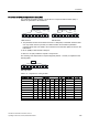
USS communication network via RS 485 with a CU240E
The diagram shows the RS 485 terminals (29/30) and the DIP
switches at the CU240E for the terminating resistor. The default
position is OFF (no terminating resistor).
2))21
*
*
*
212))2))
6FUHHQLQJ
)LQDO56VODYH
56
0DVWHU
7HUPLQDWLRQ
UHVLVWRU
&8(
56VODYH
&8(
56VODYH
&8(
Figure 5-17 USS network via RS 485
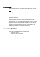
USS communication network via RS 485 with a CU240S
The connection is established using the
SUB D connector located on the lower side
of the Control Unit.
The diagram shows the DIP switch for the
terminating resistor at the CU240S. The
default position is OFF (no terminating
resistor).
2))21
68%' 68%' 68%'
*
*
*
212))2))
6FUHHQLQJ
)LQDO56VODYH
56
0DVWHU
7HUPLQDWLRQ
UHVLVWRU
&86
56VODYH
&86
56VODYH
&86
Figure 5-18 USS network via RS 485