
Operating instructions


Functions
5.10 Technological functions
CU240S and CU240E Control Units, FW 3.2
Operating Instructions, 03/2009, A5E02440075B AA
149
&RPPDQGVRXUFHV
6HWSRLQWFDOFXODWLRQ
3URWHFWLRQIXQFWLRQV
6WDWXVPHVVDJHV
)DLOVDIHIXQFWLRQV
)DLOVDIHFRP
PDQGVRXUFHV
0RWRUFRQWURO
6HWSRLQWVRXUFHV
7HFKQRORJLFDO
IXQFWLRQV
)L[HGVHWSRLQWV
0RWRUL]HG
SRWHQWLRPHWHU
-2*VHWSRLQW
3RVLWLRQLQJUDPS
.LQHWLFEXIIHULQJ
'&EUDNH
)O\LQJUHVWDUW
5DPSIXQFWLRQJHQHUDWRU
/LPLWDWLRQ
6NLS
2YHUFXUUHQW
2YHUYROWDJH
2YHUWHPSHUDWXUH
6\VWHP
SURWHFWLRQ
9IFRQWURO
9HFWRUFRQWURO
ZLWKRXWHQFRGHU
9HFWRUFRQWURO
ZLWKHQFRGHU
7RUTXHFRQWURO
,QYHUWHU
FRQWURO
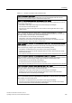
Figure 5-16 DDS switchover in the inverter
The drive data sets are switched over using parameters P0820 and P0821. Parameters
P0820 and P0821 are interlinked to control commands, e.g. the digital inputs of the inverter,
using BICO technology.
Note
Drive data sets can only be changed over in the "ready for operation" state. The switchover
time is approx. 50 ms.
Exceptions: The ramp-function generator parameters, the ramp-down time for OFF3, and the
speed controller gain can be switched during operation.