
Operating instructions


Functions
5.10 Technological functions
CU240S and CU240E Control Units, FW 3.2
134 Operating Instructions, 03/2009, A5E02440075B AA
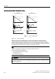
The inverter controls the dynamic braking depending on the DC link voltage.
The temperature monitoring of the braking resistor should be evaluated. The inverter must
be switched off if the braking resistor overheats.
WARNING
If a braking resistor that is unsuitable is used, a fire could break out and severely damage
the inverter.
The temperature of braking resistors increases during operation. For this reason, avoid
coming into direct contact with braking resistors. Make sure that the devices are located at
sufficient distances from each other and that proper ventilation is provided.
Parameterizing the dynamic braking
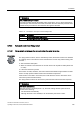
Table 5- 53 Parameters to enable and set dynamic braking
Parameter Description
P0003 = 2 Extended access
P1240 = 0
or
P1240 = 2
Deactivate the V
DCmax
controller
P1237 Enable signal and ON period of dynamic braking
0: Dynamic braking is locked
1: 5% ON period**
2: 10% ON period
3: 20% ON period
4: 50% ON period
5: 100% ON period
The ON period set here is only effective if the braking resistor has reached its operating
temperature. When required, a cold braking resistor is switched-in independent of this
parameter
**) SIEMENS resistors are designed for 5% ON period