
Operating instructions


Functions
5.10 Technological functions
CU240S and CU240E Control Units, FW 3.2
Operating Instructions, 03/2009, A5E02440075B AA
133
Parameterizing compound braking
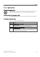
Table 5- 52 Parameters to enable and set compound braking
Parameter
s
Description
P003=3 User access level
3: Expert
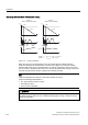
P1236= Compound braking (entered in %)
Parameter P1236 defines the DC current superimposed on the motor current after the
DC link voltage threshold V
DC link comp
has been exceeded.
P1236 = 0
Compound braking locked
P1236 = 1 … 250
Current level of the DC braking current as a % of the rated motor current (P0305)
P1254= Calculation type of the switch-in threshold V
DC link comp
for compound braking
P1254 = 0
V
DC link comp
is a fixed value that only depends on the parameterized value of the line
supply voltage (P0210).
P1254 = 1
V
DC link comp
is continually calculated using internal algorithms. This allows the inverter
reserves to be better utilized.
5.10.1.2 Dynamic braking
Dynamic braking applications
Dynamic braking is typically used in applications in which dynamic motor behavior is
required at different speeds or continuous direction changes, e.g. for conveyor drives or
hoisting gear.
An internal closed-loop chopper control (braking chopper) in the inverter, which can control
an external braking resistor, is required for dynamic braking.
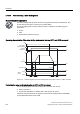
Operating characteristics of dynamic braking
Dynamic braking converts the regenerative energy, which is released when the motor
brakes, into heat.
a
a
a
'&35 '&35
,QYHUWHU
%UDNLQJUHVLVWRU
&KRSSHU
FRQWURO
Figure 5-11 Dynamic braking with braking chopper in the inverter