
Operating instructions


Functions
5.10 Technological functions
CU240S and CU240E Control Units, FW 3.2
132 Operating Instructions, 03/2009, A5E02440075B AA
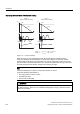
Operating characteristics of compound braking
_I_ _I_
IBVHW IBVHW
IBDFW IBDFW
WW
W
WW
W
LL
9
'&OLQN
9
'&OLQN
9
'&&RPS
3 9
'&&RPS
෬෭෬3
3ำ9
'&&RPS
෬U
3
:LWKRXW&RPSRXQGEUDNLQJ
3!
:LWK&RPSRXQGEUDNLQJ
Figure 5-10 Compound braking
When the motor is in the regenerative mode, the inverter DC link voltage increases.
Compound braking is active depending on the DC link voltage. From a DC link voltage
threshold that can be set, the inverters adds a DC current component to the motor current.
The DC current component brakes the motor, converts the regenerative energy of the motor
into heat and prevents the DC link voltage from increasing too high.
Note
Compound braking is only active in conjunction with the V/f control.
Compound braking is deactivated, if:
• The "flying restart" function is active
• DC braking is active
• Vector control is selected
CAUTION
For compound braking, the kinetic energy of the motor and motor load is partially converted
into thermal energy. The motor can overheat if braking lasts too long or the drive must be
braked too frequently.