
User manual


24 Technical Manual D2559 (TX150 S6)
Interfaces and connectors Features
3.7 Interfaces and connectors
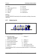
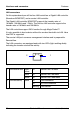
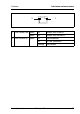
Figure 5: Schematic view of the system board D2559
1 = parallel port (optional) 15 = SATA 6
2 = CPU fan 16 = USB DAT
3 = slots for main memory modules 17 = USB intern
4 = PC98 18 = system fan 3
5 = front panel 19 = system fan 2
6 = floppy disk drive 20 = SMB1
7 = power supply ATX PWR1 21 = intrusion
8 = system fan 5 22 = jumpers (see page 28)
9 = system fan 4 23 = HDD activity
12345
6
7
15
8
10
11
13
14
17
21
27
23
26
20
24
28
9
18
19
Slot 3
CPU
DIMM1A
DIMM2A
DIMM1B
DIMM2B
iRMC
Battery
Slot 4
Slot 5
Slot 6
LAN
Super
I/O
MCH
RAID
key
Slot 2
Slot 1
PCIe x8
PCIe x8
PCIe x4
PCI 32 Bit / 33 MHz
PCI 32 Bit / 33 MHz
PCI 32 Bit / 33 MHz
CSS
button
12
16
25
22