
User manual


D2559 (TX150 S6) Technical Manual 19
Features PCI bus
PCI and PCI-X buses use four lines named INTA to INTD, typically connected
to all devices on the bus in order to periodically balance interrupt load. An
interrupt signal may thereby be used simultaneously by multiple devices
(interrupt sharing).
PCI Express devices send their interrupts through messages. This avoids
restrictions in wiring.
The following interrupt signals are used in the system:
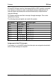
Assignment of the PCI interrupts
If you select Auto in the BIOS setup, the interrupts are assigned automatically
and no further settings are required.
Slot/device Property Interrupt signal
VGA iRMC graphic Int B
LAN BCM5755T Int A
Slot 6 PCIe x8 Int A, B, C, D
Slot 5 PCIe x8 Int A, B, C, D
Slot 4 PCIe x4 Int A, B, C, D
Slot 3 PCI (33 MHz) Int C, D, F, G
Slot 2 PCI (33 MHz) Int F, G, C, D
Slot 1 PCI (33 MHz) Int G, F, D, C