
User's Manual


Siemens PLT 111 · 1999
7/8
Coupling with other systems
Serial coupling
with SIMATIC S5/S7 central controllers
SIMATIC S5/S7 central controllers
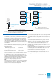
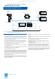
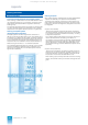
Fig. 7/3 Coupling of automation systems with SIMATIC S5/S7 central
controllers
Serial coupling with SIMATIC S5/S7 central controllers
In certain cases it may be advantageous to assign autonomous
parts of an automation program to a subordinate automation
level. There is less loading on the automation system, and valu-
able calculation time can be saved. This is especially important
in the case of automation tasks with short cycle times which may
place a heavy loading on the calculation capacity of a proces-
sor. Subordinate programs can also be developed and tested
independently of other program sections.
The following are required to couple the AS 235, AS 235 H and
AS 235 K automation systems to SIMATIC S5-115U, S5-135U
and S5-155U central controllers and SIMATIC S7-300 and
S7-400 automation systems:
• interface module for
SIMATIC S5/S7 central controllers 6DS1 333-8AB
• Connecting cable 6DS8 137-8..
• For SIMATIC S5:
CP 524 communications processor
1)
6ES5 524-3UA15
CP 544 communications processor
1)
6ES5 544-3UA11
• For SIMATIC S7-300:
CP 341 communications processor
2)
6ES7 341-1BH00-0AE0
with 20-mA (TTY) interface
• For SIMATIC S7-400:
CP 441-2 communications
processor
2)
6ES7 441-2AA02-0AE0
The interface module 6DS1 333-8AB can be inserted into any
slots for I/O modules of an AS 235 automation system or an
ES 100 K extension system. A SIMATIC S5/S7 central controller
can be connected to each of its 2 channels.
I/O bus
AS 235,
AS 235 H,
AS 235 K,
ES 100 K
Interface module
6DS1 333-8AB
max. 1000 m
.
.
.
.
..
..
SIMATIC
central controllers
S5-115U/-135U/-155U
CP 524 /
CP 544
Channel 1
SIMATIC
automation systems
S7-400 / S7-300
CP 441-2 CP 341
Channel 2
1) See Catalog ST 50 for interface modules, parameterization tools and acces-
sories
2) See Catalog ST 70 for interface modules, parameterization tools and acces-
sories
A screened, four-conductor cable twisted in pairs is used for
data transmission. The maximum distance between the interface
module and the central controller is 1000 m. Data transfer is
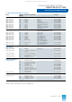
sequential via a coupling link with 20-mA current loop. The chan-
nel-specific transmission rate can be adjusted in steps:
Data transfer between the AS 235 central processing unit and
the interface module 6DS1 333-8AB is handled via the S5KS and
S5KE driver blocks in the automation system. The 3964 or
3964 R transmission procedure (selectable) is used for data
transmission between the interface module and the
SIMATIC S5/S7 central controller.
RK 512 is used as the protocol. The SIMATIC S5 sends or
fetches the data by means of messages. The TELEPERM M
interface module is the passive participant in the communica-
tion. S7 central controllers operate with SEND/RECEIVE and
S5 analog-value format.
Further information
• Catalog ST 50
for SIMATIC S5 central controllers and
CP 524/544 communications processors
• Catalog ST 70
for SIMATIC S7 central controllers and
CP 341/441-2 communications processors
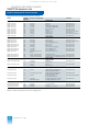
Transmission rate Max. coupling line length
300, 600, 1200, 2400 bits/s
1000 m
4800 bits/s
500 m
9600 bits/s
300 m
This catalog is out of date, see note on page 1